All other tooling will be defined in the “Operation Tool(s) Setup” section. Control Nesting has the option to setup 50 different operations. To start, choose an operation number from the pull-down menu. Then select the “Select Operation Tool” button and choose a tool. Now we need to define the operation(s) that we would like to use this tool for. This can be done by selecting the appropriate operation(s) under the “Type” section. Only now can we set the “Feed Speed”, “Plunge Speed”, “Spindle Speed”, "Max Penetration", and “Reverse Spindle”. These fields are grayed out until the operator chooses an operation type.
Tools specified as "Pocket" will be used in Pocketing operations. The pocketing feature will search through the list of Operation Tools set to "Pocket" then sort them from largest diameter to smallest diameter. On each pocket operation the tools will be used in this order until either the minimum leftover area is satisfied or the tool list is complete. “Step Percentage” is the amount the tool will step over each cut pass based on a percentage of the tool diameter.
The "Max Penetration" setting keeps a tool from being used at a depth greater than this amount in 1 pass. If a depth of cut is greater than this amount Control Nesting will perform the operation in incremental passes at the "Max Penetration" amount until the operation is complete.
The "Drill Type" setting tells Control Nesting what type of drill a particular tool number is designed to accomplish. This is where drill bank options are established.
X3 Y3 X5 Y5 CX3 CY3 CX5 CY5:
A 3 and 5 drill bank is designated in THM Tool Management by setting the tool number's actuator position number to designate the CENTER drill bit. The X bank will be a separate tool number from the Y bank. This logic was put in place to handle any different number of positions. That is why the actuator position number is critical. Control Nesting understands that the actuator position is the CENTER of the bank. If your drill bank is mounted to a C axis then the C options should be selected.
Fig. 1
Drill Bank Example:
If your drill bank is like Fig. 1 you would set the actuator position to 3 for the X axis tool number and 7 for the Y axis tool number in THM Tool Management.. Then in the Tooling section of Control Nesting you would set the Drill Type to X5 for the Operation Tool using your X axis tool number and Y5 for the Operation Tool using your X axis tool number. If you only wish to use 3 drills then you pick the center actuator position number for the tool number in THM Tool Management and then designate that Tool Operation as X3 or Y3.
Custom:
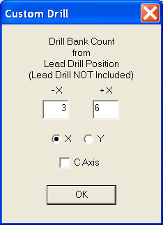
The Custom option for Drill Type gives the ability to set up larger drill banks as well as bank counts other than 3 or 5. This setting allows the designation of the lead drill along with the count of drill bits before and after. The designation is determined based on the positive (+) or negative (-) direction. In the following image a custom drill operation of 3X5 has been entered. This means that the bank is along the X axis and there are 3 bits in the negative direction from the lead bit and 6 bits in the positive direction from the lead bit. This makes a total of 10 bits. The tool number in THM Tool Management that will be selected for this operation should have an actuator position number set to the value that allows these counts to be accurate.
Notice the “Interpolate” selection. With this selected, we are allowing that tool to be used for any circle interpolation that may be needed. Also, with this selected we are now able to set the “Max Interpolate Diameter” field. The “Max Interpolate Diameter” field allows the user to limit the size of hole to machine with that tool. Normally, when drilling a hole with a high RPM, there is a risk of burning the material or damaging the tool. Interpolating a hole will prevent this from happening.
Dove Tail tool specifications can as be set with Dove Tail Tool and Dove Tail Male Routs check boxes. The Dove Tail Tool check box is to designate the tool is a Dove Tail Tool. The Dove Tail Male Routs check box is to designate this tool is to be used to cut the male ends of the dove tail joint if and only if the tool diameter is small enough to perform the radius cuts that are present in a particular joint.
Ignore Cut Through Depth will stop Control Nesting from adding the Cut Through Depth to an operation that is a through cut with this tool.
Break Through will apply the specified amount to the depth of the drill operation when the drill operation is a through cut. When enabled this value is used in place of the specified Cut Through Depth amount in Settings.
Add Depth will apply a positive or negative value to a drill operation for that tool when the hole to be drilled is not a through hole.
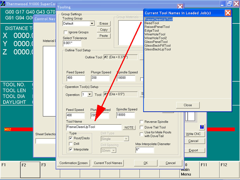
Some jobs such as MDF Doors can require special tooling. For these jobs the tool recognition is done by using Tool Names. Go to Tooling to designate these tools. Clicking on Current Tool Names button will open a dialog specifying the tool names in the currently loaded job. If the job does not contain any tool name then this dialog will not display. These tool name can be copy/paste into the Tool Name entry box for the appropriate operation tool. Now Control Nesting will select this tool for the appropriate operation in the job.
Use by Name NOT Required will allow Control Nesting to continue to obey the Tool Name designation, however, if an operation in a job does not contain a Tool Name, the operation tool will still get selected if it meets all other specified properties.