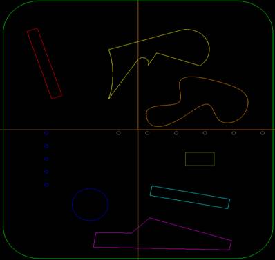
Let’s begin by opening the DXF file named “layers.dxf” in a CAD/CAM software that supports the DXF file format. Take a moment to view the different layer names and what is drawn on each of them. This is the key part in making DXF files work with Control Nesting. The layer names contain information such as type of operation, depth of cut, and in some cases, the diameter of tool to be used. Below is a picture of the DXF file:
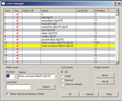
Level Manager Example:
Level Manger image of the above DXF file to illustrate the layer names, depth and tool diameter settings for each corresponding layer:
Entities may be drawn in any color. The drawing can be in metric or inches. In the Control Nesting SETTINGS option on the Thermwood controller, the FORMAT section needs to be Metric or Imperial depending on the format of the DXF drawing, this will determine the output of the CNC code. The colors being used here are for tutorial purposes only.