The User Defined Operations take information provided by eCabinet Systems software to set variables and add additional code to the CNC program.
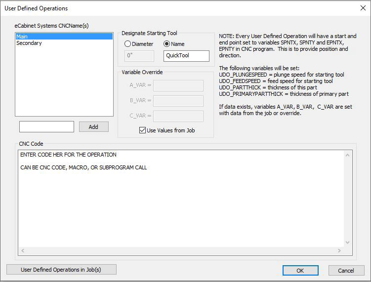
1. eCabinet Systems CNCName(s)
a. This is the CNCName used in eCabinets and Control Nesting.
b. The name must match between the two softwares.
c.
A new CNCName can be added by filling in the appropriate field and selecting
the  button.
d.
Double clicking the CNCName with the left mouse button allows the name
to be changed.
e.
A CNCName can be deleted by selecting the name and pressing the Delete key on the
keyboard.
2. Designate Starting Tool
a. This is the tool that will be called prior to starting the CNC Code.
b.
The tool must be set up in Tooling of Control Nesting, and marked as a
Rout/Dado tool.
c.
Diameter
1.
Selecting the bullet for Diameter requires input of the diameter of tool
to be used.
2.
The diameter must be the same as the tool's in Tooling, or within the
tolerance range.
d. Name
1.
Selecting the bullet for Name requires input of a tool name for the tool
to be used.
2.
The tool must be set in Tooling with a Tool Name exact to what is keyed
in this field.
3. Variable Override
a. Allows the user to override the variables passed from eCabinet Systems.
b. Checking the box for Use Values from Job, uses the variables from eCabinet Systems.
3. Variable Override
a. Allows the user to override the variables passed from eCabinet Systems.
b. Checking the box for Use Values from Job, uses the variables from eCabinet Systems.
4. CNC Code
a. This is the area to add in code for Control Nesting to add to the regular code for cutting the parts. Any information within this box will be passed on.
b. The area can be as complex as many lines of code, or be a macro call to run another set of code.
c. Standard Windows cut, copy, and paste work within the area.
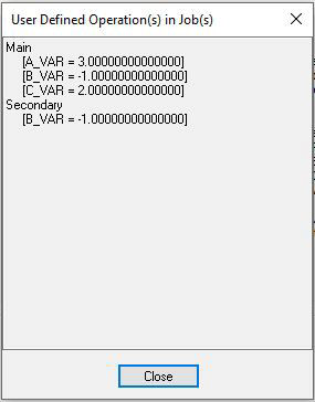
5. User Defined Operations in Job(s)
a. Selecting this button displays what User Defined Operations are used in the job(s) that is loaded.
b. Also displays the values for the variables as passed from eCabinet Systems.
Several variables are set and may be used in your CNC code. Each part has an indicator displayed in eCabinet Systems that is perpendicular to the part's edge. The indicator's starting point is the edge for the primary part. For the secondary part, the starting point is determined by where the primary part's starting point connects with the secondary part. The ending point is the other end of the indicator respectively. Below is a table listing those variables and what they reference:
|
Variable |
Description |
|
A_VAR |
VarA value passed from eCabinet Systems |
|
B_VAR |
VarB value passed from eCabinet Systems |
|
C_VAR |
VarC value passed from eCabinet Systems |
|
SPNTX |
Starting X location of User Operation indicator |
|
SPNTY |
Starting Y location of User Operation indicator |
|
ENPTX |
Ending X location of User Operation indicator |
|
ENPTY |
Ending Y location of User Operation indicator |
|
UDO_PLUNGESPEED |
The plunge speed of the tool as taken from Tooling |
|
UDO_FEEDSPEED |
The feed speed of the tool as taken from Tooling |
|
UDO_PARTTHICK |
Thickness of the part's material |
|
UDO_PRIMARYPARTTHICK |
Thickness of the primary part |
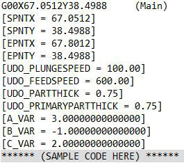
Example code from Control Nesting shown below. The line ****** (SAMPLE CODE HERE) ****** is the code entered in the CNC Code area of User Defined
.