 In the Detail Room area, Main page, under Select Item to Install select Item.
In addition to the Add Countertop Command covered earlier, Display Cubes can also be used to create countertops. Countertops can simply be rectangular cubes with the correct texture image. Complex countertops can be created by processing these Display Cubes through the Display Part Editor.
To demonstrate this approach we will use some examples. In this first example we are creating a simple rectangular top to place over a set of two cabinets.
In the Detail Room area, Main page, under Select Item to Install select Item.
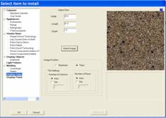
Then select Display Cube.
Input the size and then press Image to select an image for our countertop.
Press OK.
The Display Cube function places the top in the center of the room at floor level. You will need to orient the top to the cabinets and raise it to the proper height above the floor. Then it is moved into position.
 In this case we need to spin it
around 90 degrees to orient it properly with the cabinet. From the Right Click Menu, select Edit Object – Rotate Object.
In this case we need to spin it
around 90 degrees to orient it properly with the cabinet. From the Right Click Menu, select Edit Object – Rotate Object.
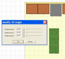
This brings up the dialog shown.
Spin the top 90 degrees on the Z Axis.
It is now ready to position.
We will next cover positioning of the countertop in detail to show some common techniques.
Here we moved the countertop using the Shift key and right mouse button to a position near where it will eventually be.
We have not moved it totally into position because it is located on the floor.
If we move too far, we will place it inside the cabinet where we will not be able to highlight it when we switch to the elevation view.
The next step is to associate the countertop to the wall so it shows up on the elevation view of the wall.
Since the countertop is already highlighted, right click on the wall and select Associate to Wall.
 Then right click on the wall again
and select Show Wall Elevation.
Then right click on the wall again
and select Show Wall Elevation.
Here we see the countertop, highlighted on the floor in the elevation view.
There are a couple of ways to move it up to the top of the cabinets.
The first, and probably easiest, is using the Edit Move Increment.
From the Right Click Menu select Edit Move Increment and change it to 34.5”.
This is the height of the cabinets.
Since the Display Cube is initially placed on the floor, moving it up 34.5” will place it at the top of the cabinets.
Simply highlight the cube and while holding the Shift key press the up arrow key one time.
The countertop is now at the correct height.
We can also use the Shift key and mouse to move it to the top of the cabinets if you are operating in the Free Style mode.
 When you get close, press the Ctrl key and pull a blue rectangle over
the top corner next to the range.
When you get close, press the Ctrl key and pull a blue rectangle over
the top corner next to the range.
The view will zoom as shown.
Now, from this zoomed view, accurately position the countertop over the cabinet edge.
Then press the Return button to return to the overhead view.
We again want to zoom in, this time on the back corner, next to the range.
Hold the Ctrl key, pull the blue rectangle to zoom as shown.
Highlight the countertop and move it precisely into position over the corner of the cabinet and up against the wall.
Press Home to return to the original zoom view.

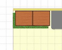
We now have a countertop on the two cabinets as shown.
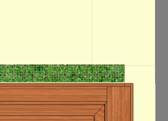
If you want, you can create another Display Cube, using the same image, to simulate a backsplash as shown.
Although at first, this appears to be quite involved, with just a little practice you will be able to place and locate these very quickly.
Now let’s address a countertop with a sink.
 There are two approaches to this.
We can’t simply move the sink over a countertop because, unless we cut a hole
in the cube, it will show in the center of the sink.
There are two approaches to this.
We can’t simply move the sink over a countertop because, unless we cut a hole
in the cube, it will show in the center of the sink.
In the first approach, we place the sink and then place several cubes around it to simulate a countertop.
Start by moving the sink into position over the sink base.
We now simply create four separate Display Cubes which surround the sink, using the techniques just covered.
 We also add a Display Cube as the backsplash.
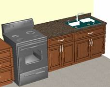
Here is the finished sink side of our layout with the countertop and sink in place.
Another approach you can use for countertops is using Display Panels.
A Display Panel is similar to a Display Cube except it is a rectangular piece of a material we defined in Settings/Preferences.
To use a Display Panel as a countertop we first need to create a new Sheet material the thickness of the countertop.
Then we must select the proper image for the material.
Now, define a Display Panel instead of a Display Cube.
The process is almost identical and the final result is essentially the same.
The only real difference is that by using Display Panels, the countertop pieces will be nested in the countertop material.
When using Display Cubes, no nesting occurs and the cubes are used strictly for display.
If you have a use for the nest information, use Display Panels. If not, use Display Cubes.
Once the countertop has been installed, you can change its texture using the Texture Match command, but you can only change it to a texture that already exists in the drawing.
This is not really a problem but does require some technique.
Create a small Display Cube with the texture you want.
Place this in the room.
Next, highlight the countertop and from the Right Click Menu select Edit Object – Texture Match.
Now click on the new textured cube.
The highlighted countertop will change to the new texture.
You will need to change each Display Cube or Display Panel in the countertop, one at a time.
Once the entire countertop is changed, you can delete the cube you used to carry the texture image.
The Part Editor offers us another way to develop countertops using Display Cubes. This is a little more involved but can produce fairly complex countertops.
In this approach, we will create the entire countertop as a modified Display Cube. Then, we will export it to the Display Part Editor, texture it and turn it into a Display Part.
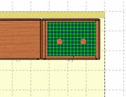
To do this we must return to the Cabinet/Assembly Editor and load a Display Cube large enough to cover all the cabinets. In our example, we create a cube that is 14’ wide, 10’ long and 2” thick.
Next, highlight it and take it to the Part Editor. Using the geometry tools and contour, cut the panel to the countertop shape you need. Notice you can cut out sink openings and even put radiuses in the corners.
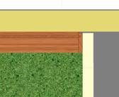
You can also put a profile along the front edges if needed.
Take these changes back to the Cabinet/Assembly Editor.
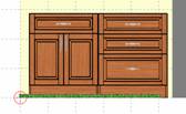
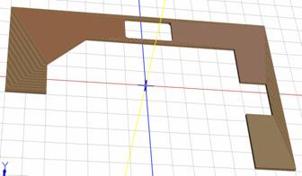 Probably the first thing you will
notice is that it is the correct shape but it doesn’t look very good. That is
because, in this area of the software, texturing is automatic and is generally
optimized for rectangular panels. These settings do not always work for
randomly shaped pieces.
Probably the first thing you will
notice is that it is the correct shape but it doesn’t look very good. That is
because, in this area of the software, texturing is automatic and is generally
optimized for rectangular panels. These settings do not always work for
randomly shaped pieces.
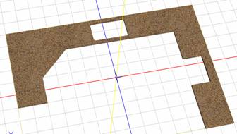
To correct this we will Export the Display Cube as an HSF file, load it into the Display Part Editor¸ adjust the texture and then save it as an HSF Display Part. We can then load this Display Part directly into our Custom Layout.
Start by pressing the Home key to access a straight on front view. If the item or items you are exporting are rotated, they will be copied in a rotated orientation and will be in that orientation when you load them into Custom Layout.
Once oriented properly, highlight the countertop by clicking on it. Then, from the File menu at the top, select Export Selection. This will export anything currently highlighted. If more than one item is highlighted, they will all export as a single HSF and become a single Display Object.
Specify a directory and name.
Now, go to the Display Part Editor. There is probably no reason to save the modified cube in the Cabinet/Assembly Editor since the texture is wrong and we already have the shape saved as an HSF.
Load the file. The texture should already look better. Generally with countertops, increasing the Texture Scale to 10 or 20 improves the appearance.
Once you have an image you are satisfied with, save it and you are ready to add it to you Custom Layout.
Note that during the save process you can specify that the countertop be added to the Cut List. You can also input a cost for the countertop that will be added to the Material Cost for the job. This is a great way to allow for the cost of countertops when estimating the cost of a job. See the chapter on Estimating Costs for more information about tracking costs in the software.
This basic approach can be used to create Display Objects within eCabinet Systems without the need for a separate CAD system. It also allows you to modify the appearance of Display Objects that you obtain from others. Simply Export the Display Object, modify the appearance in the Display Part Editor and then save it again.