When you modify a part in the Part Editor, the modified configuration of the part remains valid as long as the part size does not change. When part size changes, there are normally multiple ways Part Editor modifications can react. The Constraint Manager allows you to define how you want the part modifications to act as the cabinet size changes.
In short, this means that the Constraint Manager tells the system what to do with Part Editor modifications as the underlying part size changes.
There are two things you need to understand in this area. First you need to know how the area works to constrain or control the part shape as its size changes and then you need to understand the default behavior should you not provide any constraints.
The Constraint Manager is accessed from the Main area of the Cabinet/Assembly Editor through an icon in the top toolbar. It loads an entire cabinet and then works with any modified parts on that cabinet, one at a time. You must highlight a cabinet by double clicking on it if there is more than one item loaded in the workspace. The cabinet must be highlighted before you enter the Constraint Manager.
An interesting feature of the Constraint Manager is that you can not only constrain certain dimensions but you can also Edit them. For example, if you cut a circular hole in a panel in the Part Editor, you can change both the diameter and the position of the hole in the Constraint Manager. In some cases, creating a hole pattern for example, it might be easier to just cut the initial holes in the Part Editor in random diameter and positions using simple mouse input and then specify the exact diameter and position in the Constraint Manager. This will become clearer as we examine how the area works.
When you first enter the Constraint Manager, the first part from the cabinet is loaded. The part name is shown in the display box at the center top. If more than one cabinet part has Part Editor operations, you can list and select other parts using this dialog box. You will define the constraints for every part of the cabinet that has Part Editor operations before leaving the area. These definitions remain with the cabinet when it is saved.
Operations can be constrained on both the front and back of the part. Those operations that were performed from the front side in the Part Editor are accessed from the front side in the Constraint Manager. Those operations that were performed from the back side in the Part Editor are accessed from the back side in the Constraint Manager. Switch between front operations and back operations by right clicking and selecting Operations and either Front Ops or Back Ops.
The Constraint Manager functions by fixing of “constraining” certain dimensions. Press the “M” key to see the constraint nodes that are available for selection.
We can constrain a node either horizontally or vertically. We can also constrain the diameter of a circle or arc. The best way to understand the operation of this area is to use some examples.
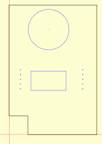
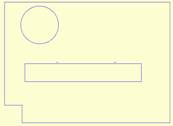
We will start with the cabinet side shown. It has a circle and a rectangle cut through it.
Let’s start by seeing what happens when the depth of the cabinet increases. In this case, we will change the cabinet from 24” deep to 48” deep.
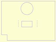
The Constraint Manager has a Test function that allows you to change the size of the cabinet and see the effect of the constraints you have defined. Press the Test button, input a new cabinet size and press Enter.
In this case, we have not defined a constraint, so the geometry maintains a proportional position with respect to the center of the part. If the geometry were located exactly in the center, it would stay in the center as the part size changed.
Let’s assume, however, that we would like the circle to remain the same distance from the front of the part as the part size changed.
 What we want to do is constrain the
center of the circle to a fixed distance and measured horizontally.
What we want to do is constrain the
center of the circle to a fixed distance and measured horizontally.
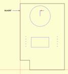
Press the horizontal constraint icon in the top toolbar. Then move the cursor over the center of the circle until the center node displays. Click.
Next, move the cursor over the upper left corner of the part until the node appears (the lower left corner also works). Click.
Now you have a small box with an X in it. This indicates where the text defining the dimension will be placed. Move it to a convenient location and click.
This capability to locate the text is provided because on some complex parts, there are a lot of constraint dimensions and they can get confusing so this allows you to position them in the nest possible location.
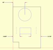
In this case, the center of the circle will remain 10.475” from the front of the cabinet.
Let’s say, however, that that is not exactly what we want. We want the center of the circle 10” from the front.
Press Edit. Then click on the 10.475” dimension to highlight it. Then, input the new dimension (10”) in the dialog box and press Enter.
 The center of the circle is now
located 10” from the front of the part. Lets double the depth of the cabinet
and see the result of this new constraint.
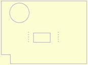
The center of the circle is now
located 10” from the front of the part. Lets double the depth of the cabinet
and see the result of this new constraint.
As you can see, the circle stayed 10” from the front of the part as the part size doubled.
This same thing works vertically with the top or bottom of the part.
Before we move on, you should note that the location of the text for any constraint can be changed by pressing the Move icon and then clicking on the text you want to move. You can then move the text to a new location and click again to anchor it.
 Now let’s look at the bottom
rectangle. In this case, we will constrain the left edge of the rectangle to
the front of the part and the right edge of the rectangle to the back of the
part.
Now let’s look at the bottom
rectangle. In this case, we will constrain the left edge of the rectangle to
the front of the part and the right edge of the rectangle to the back of the
part.
The only way to keep these two distances the same as the part size changes is for the size of the rectangle to change and that is exactly what happens as seen to the right.
In addition to horizontal and vertical constraints, you can also constrain the diameter of a circle or arc. This is not useful as a constraint today since the diameter remains constant as a default, however, once it has been constrained, you can use the Edit feature to change the diameter and this can be quite useful.
So far we have constrained geometry to fixed distances. In the current version of the software you can also use two variables, “W” for the width of the part and “H” for the height of the part. W and H can be used in formulas to define constraints. For example, W/2 when used to define a horizontal position will always position in the center of the part. W/3 is one third of the way across the part.
These formulas work using +, -, * and / and also understand parentheses.