 The Cabinet/Assembly Editor for the corner cabinet is essentially the
same as for the base or upper cabinet with two additions.
The Cabinet/Assembly Editor for the corner cabinet is essentially the
same as for the base or upper cabinet with two additions.
Corner cabinets are somewhat unique because they include parameters that other cabinet types do not share. These parameters are specific to the unique requirements of a corner cabinet.
The Cabinet/Assembly Editor for the corner cabinet is essentially the
same as for the base or upper cabinet with two additions.
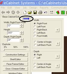
The first addition is a dialog to help define the basic dimensions of the corner cabinet. It is accessed by pressing the button with the blue arrow shown highlighted here.
This opens the dialog shown to the right of the arrow.
Base and upper cabinets have only three primary dimensions, Width, Height and Depth. Corner cabinets are more complex.
The way this dialog works is quite simple. Once you understand the concept behind it you will find it quite easy to use.
There are a lot more dimensions that must be maintained on a corner cabinet than on a standard base or upper cabinet.
Instead of adding a whole list of new dimension boxes for corner cabinets, the system keeps the same three dimension boxes, but uses a dialog to select which dimension on the corner cabinet is in those dimension boxes at any time. In the example shown, the top Width box is currently showing the Right Front Width of the corner cabinet. If you select another width for display, the title over the dimension will reflect that change.
In this way, all the various dimensions can be specified while maintaining the standard three dimension boxes.
The next obvious problem is what do all these dimensions mean?
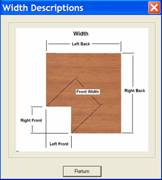 To address this, a question mark
button has been placed in each area which launches a diagram of the corner
cabinet showing the meaning of each dimension name.
To address this, a question mark
button has been placed in each area which launches a diagram of the corner
cabinet showing the meaning of each dimension name.
It is possible to specify any of the dimensions shown, however, in many cases the dimensions are interconnected. Changing one may change others, however this approach allows you to specify dimensions of the corner cabinet using the dimensions most available to you.
You will quickly notice that each side of the corner cabinet can be a different dimension, both in Width and Depth. With the other changes, you will find that corner cabinets can become somewhat complex These , are necessary to create the variety of corner cabinet designs required by most cabinet shops so we must learn to deal with the somewhat more complex approach.
The second area where corner cabinets differ from base and uppers is in Construction Settings. When you load a corner cabinet, one additional dialog area becomes available called Corner Settings.
There are three areas that are defined in the corner settings dialog.
Making a change to any of these automatically changes the corner cabinet you are working on.
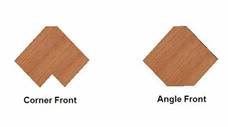
The first area determines whether the cabinet has a Corner Front or an Angle Front. Again a question mark button brings up a diagram, as shown, to help you understand the meaning of the terms used.
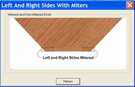
The next area determines if a corner cabinet with face frames has the left and right stile mitered parallel to the cabinet sides as shown.
Obviously this only applies to Angled front cabinets since on Corner Front cabinets the face frame is always 90 degrees to the cabinet side.
If you select Mitered, the system will designate it as mitered but the display in the current version of the software does not show the miter.
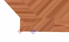
The designation of Mitered is important when placing cabinets in a Custom Layout.
The face frame of the corner cabinet is going to butt against an adjoining cabinet. The point where this butt occurs is controlled by this miter setting.
If you indicate the sides are mitered, the corner cabinet will butt against adjoining cabinets at the point marked in blue. If, however, you do not check Left and Right Sides Mitered, the corner cabinet will butt against adjoining cabinet at the point marked in red. This will be easier to understand once the display properly shows the miter, however, for now the system does make proper use of this setting when placing cabinets, which is the important point.
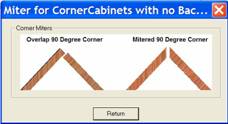 The next selection is a checkbox
that determines on a 90 degree corner cabinet with no Corner Gap (we will cover that in a minute), whether the two back panels
overlap or are mitered.
The next selection is a checkbox
that determines on a 90 degree corner cabinet with no Corner Gap (we will cover that in a minute), whether the two back panels
overlap or are mitered.
A 90 degree cabinet is the only angle at which this option exists. Otherwise, the back corner is always mitered.
If you select overlap, one back panel is cut shorter than the other, providing the overlap. This can be machined with only 90 degree vertical cuts.
If you select mitered, both panels are made long enough for the miter cut, however, the back edge of both panels must be mitered at the correct angle before the panels fit together at the back.
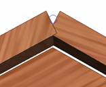 Here again, the actual miter is not
displayed but the individual components are made long enough so that the miter
can be cut on each.
Here again, the actual miter is not
displayed but the individual components are made long enough so that the miter
can be cut on each.
For display purposes, they are meshed as shown.
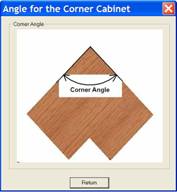
The next parameter that you can adjust is the Corner Angle.
This is simply the angle that the two back panels make with each other. Angles from 90 to 179 degrees are possible.
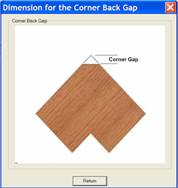
The final corner setting is the Corner Gap. Once a corner gap is specified, a third back panel is added.
The three back panels are always mitered.
Again, the actual miter is not displayed in the software but instead the parts are made large enough to accommodate the miter and then are meshed for display. Again you must realize that the proper miter angle must be cut on the part for them to assemble properly.
These are the basics of corner cabinets but, with these controls a huge variety of cabinets can be created.