Drawer boxes are designed in an area called Drawer Box Designer. This is actually a stripped down version of the Cabinet/Assembly Editor configured specifically to design drawer boxes. Many of the controls are the same.
As with cabinets, you start with an initial “seed” drawer box, modify it and then save it under a new name. The modified drawer box can then be loaded, further modified and saved under yet another name. Unlike cabinets, however, drawer boxes can be saved and retrieved from any directory so it is important to remember where you put them.
Also unlike the Cabinet/Assembly Editor, the Drawer Box Designer only has two ways to modify the box, change the size or modify drawer box Construction Settings. There are no Editors since, unlike a cabinet, there is nothing extra to add or configure on a drawer box. The Drawer Box Designer has its own Construction Settings that pertain to drawer box design and construction. As with cabinets, each drawer box has its own Construction Settings that are part of the drawer box itself and define that particular drawer box.
The Drawer Box Designer is accessed from pretty well anywhere in the software through an icon in the top toolbar.
If you are in the Door/Drawer Editor or in the Drawer Box Editor, you can access the Drawer Box Designer using the button Drawer Box Selection.
If you are loading drawer boxes into the Cabinet Assembly Editor workspace using Load Item – Drawer Boxes, you can access the Drawer Box Designer through the button Select Drawer Box.
In short, any time you need to add a drawer box, the Drawer Box Designer pops-up where you can either load and use a drawer box design you previously saved or load a saved design and modify it into a new one. Now let’s look at the operation of the Drawer Box Designer.
The process starts by loading an existing drawer box. There are two initial drawer boxes that are part of the system. Each can be modified and saved under new filenames. They are found under eCabinets/drawers/Saved/Slab/Standard. Unless you save a modified drawer box to another directory the system should take you to the above directory.
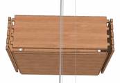
The two standard drawer box designs offered represent the two basic ways dovetail drawer boxes are made. Both use a bottom material that is not as thick as the sides and is full dadoed into the front and sides. One box also full dadoes the bottom into the back, completely capturing it. The second design stops the back short so that the drawer bottom can be slid into the box from the back and pin nailed or stapled in place.
This second design allows the bottom to be removed for finishing the interior of the drawer box, eliminating blow back from the spray gun. The drawer bottom is then assembled and stapled in place after finishing.
Once the standard design is loaded we have a workspace that functions the same way as the Main page of the Cabinet/Assembly Editor. The drawer box image can be moved, rotated and zoomed using the same mouse controls as the cabinet (Shift + Left Mouse Button to rotate, Shift + Right Mouse Button to move and Shift + Both Mouse Buttons to zoom). Note that the cursor needs to be inside the workspace window for these controls to work.
Also, the drawer box can be exploded using either the slide bar control or the wheel on your mouse. Reset View also works the same and you can use the arrow keys just like the Cabinet/Assembly Editor.
Workspace controls are also the same as the Cabinet/Assembly Editor. There is a slidebar to darken the background. There is also grid and axis designator controls available by right clicking and selecting Grid Settings. Please refer to these controls in the Cabinet/Assembly Editor area for details of their operation.
The drawer box Width, Height and Depth refer to the size drawer box that is displayed and saved. This size will generally be adjusted when the drawer box is actually used, so select a size here that is typical of what you might need.
The drawer box is initially presented to you in the same orientation as it would be placed in a cabinet. You are looking at the front of the drawer box as you look at the front of the cabinet. The front is the panel that is facing you. The back is the panel away from you that would be in the back of the cabinet.
From this, the left side, right side and bottom are easy.
Details of the drawer box are adjusted by right clicking and selecting Construction Settings. As with the cabinet, if you right click on a particular component, Construction Settings open to that area. Otherwise you reach each area by clicking on the top tabs.
There is also a Construction Settings icon on the small toolbar at the top which will open Construction Settings.
Let’s start with the sides. Go to the Left Side area of Construction Settings (the Right Side area is identical). You will notice in Construction that in addition to the normal joints there is also a Dovetail joint. Dovetail drawers are considered high quality and we have developed a method of making these and machining them in a nest using a Thermwood CNC router with all machining begin performed from the top in a nest. This requires a special dovetail tool that includes a radius at the top. This top radius mates with the curved inside corner that results from machining the mating part using a small diameter straight cutter.
The tools required for this are available through the program.
Insets modify the side from its normal size. Positive insets make the dimension smaller and negative insets make it larger. When a drawer box is resized, the inset is based on the new size. For example, if you set a 1” inset for the top, the top will be 1” shorter than the normal height of the drawer box, regardless of what that height is.
The overlap between the sides and the front and back are specified in the front and back areas. A diagram is shown which represents the drawer as viewed from the top. The vertical pieces are the sides and the horizontal pieces are the front or back.
This can get a little confusing because the overlaps are specified in the front and back areas but the joint (construction) is specified in the left and right side areas.
Normally you will want front and back flush for dovetail joints and side flush for blind dado and other joints. Again, when we say “back flush” it means that the back overlaps the sides. When we say “side flush” it means the side overlaps the back.
Most drawer boxes use a thin bottom that is full dadoed into the sides, front and back. For drawers with a thick bottom, blind dado construction works well. In this case, you might want to go to the Bottom Construction Parameters and set all the tenon insets to zero in the Placement area. This creates a bottom that is similar to a raised panel as shown.
Now let’s address Construction Parameters. Construction Parameters are the details concerning geometry of the joints.
Each drawer box component has its own Construction Parameters and you can adjust each independently. You can also go to the Global Settings area and adjust certain parameters for every joint on the box. If you wish to change every parameter except one, it might be easier to change them all in Global Settings and then go back and adjust the one part that is different.
Except for dovetail settings, Construction Parameters are the same as found in the Construction Settings area of the Cabinet Assembly Editor. The Construction Parameters here however, only apply to drawer boxes. Changing a setting here does not affect the same setting as it applies to cabinets.
For full dado, blind dado and KD/RTA joints, we refer you to the description found in the Cabinet/Assembly Editor area. Although these settings only affect drawer boxes, they function the same way here.
Dovetail settings are grouped into two areas. The top area defines the placement of the dovetail tabs along the edge. The bottom area defines the geometry of the dovetail joint itself. For purposes of this manual we will refer to the male portion of the dovetail as the “tab” and the female pocket into which it fits the “socket”.
In defining placement along an edge, we will define the point at which the first dovetail starts from the edges of the part. We define the width of the pin. We also specify the maximum distance we want between pins. As the part size grows, the system separates the pins farther and farther apart, keeping the pin width the same. When the maximum separation distance is reached, the system adds another pin and reduces all separations accordingly.
The Front Inset and Back Inset define how far from the front and back edges to the beginning of the first pin. This distance remains the same regardless of changes in size.
You will notice that there are settings for the top, bottom, front and back edges. The software supports dovetail joints on all four edges of each part, however, for drawer boxes you will normally only deal with the front and back edges. You do however, need to input valid dimensions for all four edges or the system will not allow you to proceed.
The final placement dimension you need to define is called Max Distance Between. This is the maximum distance between pins, as measured from center to center. The actual center to center distance may be smaller than this, but will never be larger.
Next, we must define the geometry of the dovetail itself. This is done at the area at the bottom. While you are free to put any dimensions you want here and they will display properly, to actually machine the joint the dimensions must correspond to a specific dovetail tool set.
In order to machine dovetail joints in a nest, a special dovetail tool is needed that has a radius at the top. This means that each tool only works for a specific dovetail depth. The top radius also corresponds to the radius of the straight tool used to machine the pin. Dovetail tool sets are available through the program, which include the correct settings for this area.
![]()
![]() The one dimension you can freely adjust,
in addition to pin (dovetail) width, is the Corner
Angle. This is the angel on the pin. Here you see the same joint, the first
with a 40 degree angle and the second with a 10 degree angle. As you see, the
overall pin width stays the same, so to maintain the strength necessary you may
need to adjust Dovetail Width with
higher angles.
The one dimension you can freely adjust,
in addition to pin (dovetail) width, is the Corner
Angle. This is the angel on the pin. Here you see the same joint, the first
with a 40 degree angle and the second with a 10 degree angle. As you see, the
overall pin width stays the same, so to maintain the strength necessary you may
need to adjust Dovetail Width with
higher angles.
As with other areas of the software, use the display to view each change as you make it and adjust parameters until you get what you want.