
MDF doors work like other doors in that we define a design, save it under a new filename and then make that filename the default so that design is used when we add a door.
MDF door design uses tool files (.tol) for the outside profile and inside shape. In designing an MDF door, we specify a tool for the outside profile. We then select a tool for the inside profile and define the path that this inside tool takes. This path is defined in the same manner as the Thermwood doors.
Note that the path defined using the definition tables is the path of the center of the tool.
Tool shape files (.tol) are available in the software for those profile tools that can be purchased through eCabinet Systems. In addition, there are several asymmetrical MDF door tools you can use to create modeled door designs that look very much like a five piece door. Use of asymmetrical tools is covered later in this section.
You can also create your own tool files using the Shape Manager. If you want to use a custom profile tool, you need to create it prior to starting the development of the MDF door. Now, let’s design a door.
Start the Door/Drawer Front Designer (it will launch whenever you need to select a door or you can click on the Door/Drawer Front Designer icon from the top toolbar).
Under Source select MDF. Next we need to load an existing door. An MDF Standard door is available in the Standard directory if you have not saved any of your own designs yet. This is a basic door without any cuts or profiles.
This might be a good time to rename the door and specify the directory you want it saved in.
The Material selection allows you to select the sheet stock you want the door made from.
If you select Build In House, this is the material that the doors will be nested on.
If you select Alternate Source, the Material selection will define the color and texture used to display the doors but, the doors will not nest but will instead appear in the Buy List. Also, if you select Alternate Source, the Alternate Source Door pricing will be used to calculate cost for the doors.
As with the other types of doors, you have the viewing window to the right and the ability to see a full screen view of the design.
The process of configuring an MDF door consists of selecting the profile tool for the exterior edge and a tool for the interior profile. Then we specify a path for the centerline of the tool to develop the interior profile. Let’s look at these steps, one at a time.
To select the profile tools, press the Tools tab.
Tools that can be purchased through the program are already available as .tol files as are some sample asymmetrical tools intended for MDF doors. They can be found in the eCabinet/My Profile Tools/MDF Asymmetrical Tools directory.
Custom tools for use here can also be created and saved in the Shape Manager. See the section Using the Shape Manager for detail instructions for creating custom tools.
Start with the exterior profile. Press Select Tool, then find and select the tool file you want for the exterior edge of the door. Press View to see an image of the tool.
At this point, we need to set the plunge depth. Most tools are designed with the zero point at the center bottom of the tool profile so plunge depth is a negative number for cuts into the part. When you enter a number and press Apply you will see the effect of the plunge depth.
The Tool Diameter is the diameter specified when the tool profile was created. The profile will be shifted away from the center of the part by half that diameter to just meet the edge of the part. If you check Apply Radius Comp, the tool will also be shifted at the machine to allow for any difference between the actual diameter of the tool used and the Tool Diameter specified here.
Additional Offsets are used to shift the tool either toward or away from the part by an additional distance for whatever reason you might want.
There is also a checkbox that determines how the system handles corners. This setting depends on how the door will be machined. If it is to be machined using a profile tool, leave the box unchecked and the corners will be rounded to represent the rounded corners that result from this type of machining.
If the center cut is to be modeled, check the Miter Edges box and the corners will be squared off to simulate the look that results from modeling. Note that when using an asymmetrical tool, the profile must be modeled so the Miter Edges box should be checked.
MDF doors use essentially the same tables as the Thermwood doors covered above. In this case, however, the path specified by the definition tables is the centerline path for a profile tool.
There are three types of center shapes that can be cut into an MDF door, Square, Arch and Cathedral.
A Square door essentially looks like a frame with a raised center panel. Stile and rail widths can be specified, although remember that the width specified here is the distance from the edge of the door to the center of the tool that cuts the center profile. The actual width of the stiles and rails will be less depending on the tool design. It does require that both stiles be the same width and both rails be the same width, however, the stiles can be a different width than the rails.
 The second type of door supported
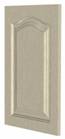
is an Arch door. An Arch door has an arch cut into the top
rail as shown to the right. The height of the arch is specified in the Arch input box. The arch is essentially
a segment of a circle.
The second type of door supported
is an Arch door. An Arch door has an arch cut into the top
rail as shown to the right. The height of the arch is specified in the Arch input box. The arch is essentially
a segment of a circle.
It is also possible to specify a side flat on each side of the arch as shown to the left.
This is specified in the table and the side flat can be made to vary with the width of the door. Note that the doors shown here all have the Miter Edges box checked.
Essentially the way this table works is that the software uses the door width to look up in the table the size of the side flats. The one caution is that if the door size qualifies for more than one specification, the system will use the last entry in the table that the size qualifies for.
For example, if you set 0 to 17 inch as a 2” flat and 17 to 24 inch as a 3” flat on the next line, a 17” door qualifies under both specifications. In this case, the last entry, 17 to 24 inch gets executed. As a final note, set the entries in order, starting with the narrowest and ending with the widest, otherwise the system gets confused.
 Preview
Size lets you specify the size of the door shown in the preview window. By
changing this size you can see the basic effect of the entries in the table. Be
sure to press the Reset View button
each time you make a change to see the effect of the change.
Preview
Size lets you specify the size of the door shown in the preview window. By
changing this size you can see the basic effect of the entries in the table. Be
sure to press the Reset View button
each time you make a change to see the effect of the change.
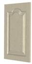
The final and most complex door is the Cathedral. A Cathedral door has a center arch with two reverse arches, one on each side. The radius of each reverse arch is expressed as a percentage of the radius of the center arch. All three arches are adjusted to meet this ratio requirement while achieving the arch height specified.
 Setting parameters for a Cathedral door is the same as setting
parameters for the flats on an Arch
door. You specify a width range and then specify the settings for any door that
falls in that range.
Setting parameters for a Cathedral door is the same as setting
parameters for the flats on an Arch
door. You specify a width range and then specify the settings for any door that
falls in that range.
In addition to the minor radius, you can also specify side flats and a top flat for a Cathedral door. The door to the right has one and a half inch side and top flats.
You might also note that when displaying MDF doors that have a grain, the grain runs the same direction across the entire door as it would if it were made from a single piece versus the grain running in a different direction for stiles and rails as it does when making a five-piece Thermwood door. This simulates the appearance you would get from laminating a foil over a machined door.