All dimensioning until now has been measurements in two dimensions. This is specified by the 2D icon. The system also allows for three-dimensional dimensioning. The three-dimensional mode is entered by selecting the 3D icon from the toolbar.
When working in the three-dimensional mode, the distance measured between two nodes is the absolute three-dimensional diagonal distance in space. This is a powerful tool for certain applications but it can also be confusing in some circumstances and can lead to drawings whose dimensions appear to be wrong. We will cover this in detail after we demonstrate the use of 3D dimensioning.
Before we start, notice that the 2D toolbar icon is blue with a red underline. If you also look carefully you will see that the dimension lines while working in 2D are blue with red arrows, the same as the colors of the icon.
The 3D icon is red underlined in blue. You will soon see that dimension lines created in the 3D mode are red with blue arrows, the same as the 3D icon and opposite of the 2D dimensions. Therefore, when looking at a drawing you can instantly tell if a dimension was created in 2D or in 3D. This is IMPORTANT!
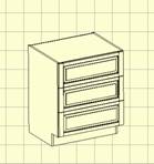
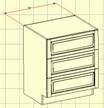
To demonstrate 3D dimensioning we copied the base cabinet and pasted it on a new page. We then highlighted it and holding the Shift key and using the left mouse button, we rotated it into this isometric view.
We now select the 3D icon to put us in the 3D mode.
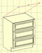
We will now introduce a new Drafting Mode called Free Form. In all the Drafting Modes so far, the extension lines from the node to the dimension line were essentially fixed. Their angle was set and could not be rotated. In the Free Form mode, the extension lines can be tilted to whatever angle is appropriate for proper presentation.
 The examples to the left show the
same dimension line moved about. This demonstrates the flexibility in
positioning the dimension. The actual dimension is the distance in
three-dimensional space between the two selected nodes.
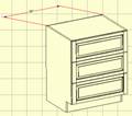
The examples to the left show the
same dimension line moved about. This demonstrates the flexibility in
positioning the dimension. The actual dimension is the distance in
three-dimensional space between the two selected nodes.
Also, in selecting the nodes in 3D, the zoom feature works the same as in 2D.

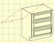
 As you can see, 3D dimensioning
offers a high level of flexibility and is especially valuable when dimensioning
isometric drawings.
As you can see, 3D dimensioning
offers a high level of flexibility and is especially valuable when dimensioning
isometric drawings.
This same capability, however, can cause problems if it is used to dimension two-dimensional drawings or Line Drawing Objects that are positioned in a standard orientation where it appears to be a two dimensional line drawing.
 Here is a good example of how you
can get into trouble using the 3D mode when dimensioning a 2D drawing.
Here is a good example of how you
can get into trouble using the 3D mode when dimensioning a 2D drawing.
Look at the actual dimension on each side of the cabinet. Both dimensions were created in the Vertical dimensioning mode and both appear to show the height of the cabinet.
One, however, shows the cabinet to be 34.50” high and the other shows the same cabinet to be 34.86”high. They cannot both be correct, or can they?
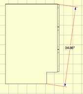
Actually, they are both correct, they are just not measuring the same thing. The dimension line to the right, the blue line with red arrows, is a 2D line that measures the height from the floor to the top of the cabinet. The second line, the red line with blue arrows, actually measures the diagonal from the top of the cabinet to the bottom corner of the toe kick as shown. In the front view above, the angle of the dimension line cannot be seen and the viewer naturally misinterprets what the line is measuring. You must take great care when using 3D measuring to not create misleading dimensions like these.
 The problem is even more confusing
if you use 2D when dimensioning an isometric view.
The problem is even more confusing
if you use 2D when dimensioning an isometric view.
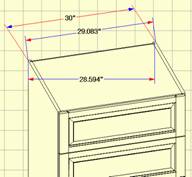
Here we see three different dimensions between the same two nodes. All are correct but all do not measure the same thing.
The 29.083” dimension is the diagonal distance between the two nodes AS MEASURED ON THE XY PLANE. The 28.594” dimension is the horizontal distance between the two nodes AS MEASURED ON THE XY PLANE. Both of these lines are in blue, indicating that they are 2D measurements. Since the cabinet is not oriented so that you are measuring two dimensional distances, they appear to be incorrect when applied to the cabinet. These dimensions actually depends on the angle at which the object is rotated and have no practical use other than knowing how far the two nodes are apart on the page.
When a person sees a dimension like this between two points, they automatically make an assumption as to what the dimension is measuring, and normally they assume it is measuring a distance on the cabinet. Make sure that the dimension you present is measuring the thing people would normally assume you are measuring.
To avoid these problems, you should restrict the use of 3D measuring mode to isometric rotations and use 2D measurement only when working with a cabinet oriented in a standard 2D orientation (front, side, top, bottom, back). Another way to check for this is that ALL dimension lines should be RED for an isometric drawing and ALL dimension lines should be BLUE for a 2D drawing.
As you work with drawings you will find that a Line Drawing Object can be freely rotated until a dimension is added. Once a dimension is added, the object cannot be further rotated.
An object can be zoomed at any time, even after dimensions have been added. The text size for dimensions on an object does not change in relation to the drawing page as the object is zoomed. Whatever the text size specified, it will remain unchanged with respect to the drawing page as the size of the object increases or decreases. You must highlight the text and use Font Control if you need to change text size.
Once dimensioning is completed, there are some additional features that can be added to the drawing. The first of these is a Leader.
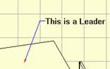 A Leader is a line with an arrow pointing to something and perhaps
text on the other end describing what we are pointing to.
A Leader is a line with an arrow pointing to something and perhaps
text on the other end describing what we are pointing to.
A Leader is placed by first selecting the Insert Leader icon from the toolbar or selecting Leader as the Drafting Mode from the Right Click Menu. Now, click where you want the tip of the leader arrow, pull out the leader line and click where you want the tail. Now, type the text you want and press Enter.
Once the leader has been placed, the position of the tail and text or the position of the entire leader can be adjusted.
To leave the arrow tip fixed and move the tail and text, click on the text to highlight it and which holding the Shift key, move the text using the left mouse button. To move the entire leader including the text, hold the Shift key and use the right mouse button.

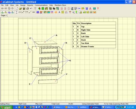
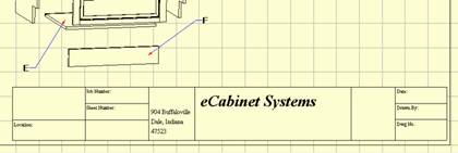
Shown here is a typical assembly drawing for our cabinet using leaders to designate each part. Notice that the three drawer fronts use a single call letter. This was done by inserting the first two leaders without adding text and then adding the call letter for the third leader. You will need to highlight and reposition the text after it is placed because to the way text is initially placed.
We will use this drawing to demonstrate another feature, tables.
 A drawing like this is often
accompanied by a lined table listing a description of each part. We will now
add such a table.
A drawing like this is often
accompanied by a lined table listing a description of each part. We will now
add such a table.
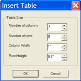
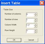
Click the Insert Table icon on the toolbar and the dialog to the right appears. We will create a table with three columns and eight rows. Press OK.
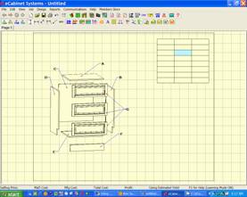
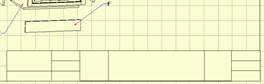
The table is inserted onto the drawing in the center. Hold the Shift key and using the right mouse button move the entire table to the upper right corner of the drawing as shown.
 Next, we will move the vertical
lines to the left as shown. As you move the cursor over the lines, they turn
magenta, indicating that the system see them. If you click on a magenta line,
it highlights in blue. The blue highlighted line can be moved by holding the Shift key and using the left mouse
button.
Next, we will move the vertical
lines to the left as shown. As you move the cursor over the lines, they turn
magenta, indicating that the system see them. If you click on a magenta line,
it highlights in blue. The blue highlighted line can be moved by holding the Shift key and using the left mouse
button.
 If more than one line is
highlighted, they will move together, maintaining their position with respect
to each other. Also, the outside lines defining the perimeter of the table can
also be moved. To the left we have highlighted the three left vertical lines
and moved them farther to the left, stretching the table.
If more than one line is
highlighted, they will move together, maintaining their position with respect
to each other. Also, the outside lines defining the perimeter of the table can
also be moved. To the left we have highlighted the three left vertical lines
and moved them farther to the left, stretching the table.
Now we are ready to add text to the table. Text is added by holding the Shift key and clicking on a cell. The cell turns green and then you can type into it. Use the Backspace to erase text. Note that you can highlight more than one cell and any text typed appears in all highlighted cells as shown. Use the Esc key to remove highlights.
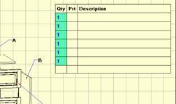
Here is the result so far.
To demonstrate other table features, let’s create a title block at the lower right of our drawing. This time we will specify six columns each 1 ½ inches wide and 1 row, one inch high.

Here we see our table after it was moved to the lower right of the drawing. We will now adjust the vertical lines.

Here we have moved the lines and have highlighted the far right cell. We will split this cell into three horizontal cells. Using the Split Cells icon, we specify one column and three rows. This means that this cell will be subdivided into one column and three rows.

Here you can see the cell we just split. We now highlight the two left cells and will split these in half.
After splitting them in half, we moved the line down and split the right cell again. We have now completed our title block.
We have added titles to some of the cells but have not added specific information about this particular drawing such as drawing numbers, etc. We can now copy and paste this title block to other drawing pages in this job. To copy, highlight any cell and press Ctrl C. Go to the next page and click anyplace on the page then press Ctrl V. The title block will be pasted in the same location on that drawing page as on the original. Any table can be copied and pasted in this manner.

You can also place text on the drawing in any location. Set the font you want and then press the Note icon. Click on the drawing where you want the text located and type the text you want.
Once placed, text can be highlighted and moved as needed.
Also, you can copy and paste text from other applications using the Windows copy and paste commands (Ctrl C to copy and Ctrl V to paste.
 One final area to cove for text
placement, which applies everywhere text is placed, is Text Line Spacing in Drafting
Parameters. Again, Drafting
Parameters are accessed through an icon on the toolbar.
One final area to cove for text
placement, which applies everywhere text is placed, is Text Line Spacing in Drafting
Parameters. Again, Drafting
Parameters are accessed through an icon on the toolbar.
This offers a familiar control over the line to line text spacing. As with other Drafting Parameters, changes here affect any new text added as well as being applied to any text that was highlighted when the change was made.
 The next area we will cover in the Line Drawing Editor concerns the density
of the drawings lines. Because of the technique used to create the image,
sometimes lines are broken and not solid as shown in the highlighted area to
the left.
The next area we will cover in the Line Drawing Editor concerns the density
of the drawings lines. Because of the technique used to create the image,
sometimes lines are broken and not solid as shown in the highlighted area to
the left.
It is also possible that interior lines defining shelves or other interior components could bleed through to the front surface.
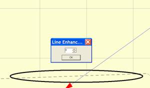
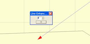 Because of this effect, which can
vary from system to system, an adjustment has been provided. This adjustment is
called Line Enhance and is accessed
through an icon on the Line Drawing
toolbar.
Because of this effect, which can
vary from system to system, an adjustment has been provided. This adjustment is
called Line Enhance and is accessed
through an icon on the Line Drawing
toolbar.
Increasing the number makes the lines more dense. Decreasing the number makes the lines less dense and will eliminate bleed through if it exists.
You need to find the best balance for your applications. Here, we changed the setting from 0 above, which resulted in a broken line, to 3, which closed the line and made it solid. 3 is the system default unless you change it. These changes are on a page by page basis so if your change it for this page, the change will not be applied to any other drawing pages. Each drawing page must be adjusted independently.
The final area we will cover in the Line Drawing Editor is Cabinet Numbers. When cabinets are placed in a Custom Layout each is given a number. This cabinet number is used to identify the cabinet in all areas of the software. If you run a Cut List, Buy List or other reports, you will find cabinets identified by their cabinet number. These cabinet numbers are also associated with the Line Drawing Object of the cabinet in the Line Drawing Editor.
To display the cabinet numbers, click on the Cabinet Number icon in the Line Drawing Editor toolbar. Cabinet numbers, in the current font and text size, are placed over each cabinet.
Once placed, these numbers can be highlighted and moved as needed. Make sure you don’t move them over another cabinet. You can press the Cabinet Number icon at any time and return the cabinet numbers to their initial default locations over the cabinets.
This completes our overview of the Line Drawing Editor. As you have seen it offers a powerful tool for creating almost any type of drawings needed.