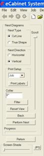
 At the very top is a selection for Nest Type. Two selections are available,
Cut Line and True Shape.
At the very top is a selection for Nest Type. Two selections are available,
Cut Line and True Shape.
If we are going to cut the parts out using any technique other than nested based CNC machining we will need to lay them out on full sheets of material. This is a process that has become known as “nesting”. When this process is complete, we will also know exactly how many sheets of material will be needed for the Job. This nesting process can be done by the software.
If we are going to process the parts on a CNC router, we really don’t need to nest the parts here in the software, since the final nesting process will be done at the machine. There is a reason, however, to nest the parts in the software even if you are going to use a CNC.
Once a Job has been processed through nesting, the software knows exactly how much material is needed. Then, and only then, will the Cost Sheet be really accurate. Until the nest is run, the Cost Sheet uses estimated yield to calculate cost. Once the nest is run, it uses the actual cost, because it knows exactly how many sheets it will take to make the parts.
The nesting area is also where you can get printed diagrams of the layout of parts on each sheet and shop drawings of each part.
Before we actually perform a nest, let’s take a look at the available controls.
The nesting area is accessed through an icon in the top toolbar.
At the very top is a selection for Nest Type. Two selections are available,
Cut Line and True Shape.
These define two different methods of developing the nest. The one you select depends on how you will process the parts.
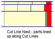
A common way to cut parts from sheets is to cut them into panels using a panel saw or table saw and then perform any additional machining on the rectangular panels.
To be able to do this, however, requires that the parts be lined up along cut lines. We need to be able to cut all the way through the sheet separating panels without cutting into adjoining parts.
This is called a “Cut Line” nest. Parts are lined up along cut lines.
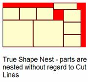
If parts are to be machined on a CNC router there is no real need to line them up. In fact, for odd shaped parts we could actually interweave them.
This approach is called “True Shape” nesting and, depending on the Job, can save material and result in better yield.
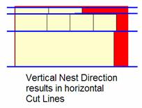
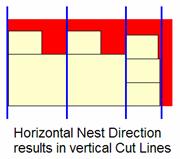
The next selection is the Nest Direction.
This determines whether the software nests the Job across the bottom first and then vertically or up the side first and then across.
In True Shape nests, this can affect the yield, so both directions should be tried and the one with the best yield used.
For Cut Line nests, this determines whether the first saw cuts are rip or cross cut.
We will skip the Print area for now and jump down to Collar.
Sheet stock seldom has edges that are smooth, square and finished adequately enough for cabinet applications. Therefore, it is usually necessary to trim the outside edges when we are machining the sheet.
In order to do this, we must allow some material around the entire edge of the sheet. This trim material around the edge of the sheet we call the Collar.
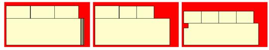
Above are nest diagrams for three sheets of material using a 2” collar.
Normally an eighth to a quarter of an inch is sufficient for most applications but we used a large collar here to make it easier to see the effect.
The Collar dimension is reserved around the entire sheet and parts are not nested into this area.
The next area to consider is the width of the saw blade or router bit.
Both of these parameters are defined in the Standard Dimensions area of Settings/Preferences. There are two input fields, Saw Blade Kerf and True Shape Nesting Cutter Diameter.
If you select Cut Line nest, the Saw Blade Kerf width is used between parts.
If you select True Shape nest, the True Shape Nesting Cutter Diameter is used, although this is not necessarily the gap between parts.
The actual space in True Shape nesting is slightly larger than the tool diameter. The software creates the program to cut each side of each part independently.
This is because you cannot ever get exactly the diameter tool you want.
To get accurate sized parts, the program must be adjusted for the exact diameter of the tool by a feature called Tool Radius Compensation. For this to work, each edge of each part must be cut separately.
The only thing you need to know is where the separation between parts comes from (Settings/Preferences – Standard Dimensions) and that for True Shape Nesting the result will be the same using a tool that is approximately the diameter you specify.
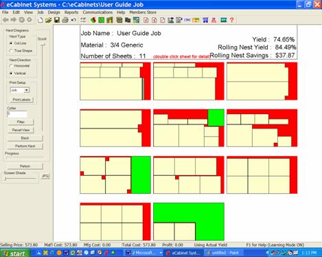
Above is a typical output for a Cut Line nest. Let’s look at the various features of this output.
At the top is the Job name and the material. If the Job uses more than one material, nests for each material are grouped together. The vertical Scroll bar is used to scroll down the list of sheets.
The total number of full sheets is shown, in this case 11.
The yield for this Job is shown assuming that all 11 sheets are used and that you discard any material left over. There are also two lines concerning Rolling Nest Yield. This is a good time to examine nests, yield and a concept called Rolling Nest.
If you look at the nest diagrams, you will see different colors.
These colors actually have meaning.
Tan parts are the actual parts needed for the Job.
Red areas are scrap.
Green areas are also scrap for purposes of the standard yield calculation, however, they are large enough to be used on new jobs if some way could be found to use them. This is where the concept of Rolling Nest comes in.
If the system knew the sizes of material or drops left from the last job, it could start by nesting parts on those pieces and then continue the job using full sheets. Although this is a simple idea, its execution in the real world is a bit tricky.
The most obvious approach is to simply keep tract of the drops in the computer and then use them the next time you run a nest. As simple and straightforward as this sounds, it presents some serious problems in a real shop.
When you use the drops in the new nest, you need to somehow communicate back to the machine which drops to use, in what order and how to orient them for machining. This is not all that easy.
Sometimes, it can be awhile between jobs that use the same material. What if the operator can’t find the drops he needs after the programs are written for them? What if they were used for something else? In the real, practical world, the simple straightforward approach does not work. It commonly costs more trying to use this material than you possibly save in improved yield.
Many of these problems disappear if you can create the nest and CNC code at the CNC machine, rather than in the office. At the machine, just before you are ready to run the job, you know exactly what material you have handy. It is right there in front of you.
If there was an easy way to identify the drops and tell the control the order in which you want to run them, it would actually be practical to use them.
This is the basic idea behind Rolling Nest.
In addition to creating nests at the control, the Rolling Nest package also includes two printers. One prints a diagram of each nested sheet, identifying parts on that sheet. The second prints an adhesive backed label for each part.
The operator uses the diagram to identify the parts and places a label on each.
In addition to normal text information, some of the part labels also have a bar code. Actually two different types of parts have a bar code on their labels. The first includes all parts that need to be machined from both sides.
Some parts have machining operation on both sides. They need to be turned over and located and then the back side machined.
There are two requirements for this. First you must properly orient the part for the flip operations and then you must load the correct CNC program. The part label accomplishes both.
When the label is placed on the part after the front side machining is complete, it is always placed in a specific location. The location of the label is then used to properly orient the part when it is flipped over.
The part label also has a bar code. This bar code tells the control what CNC program to load. Just scan the label, locate the part and press Start.
The second type of part that has a bar code on its label is a drop.
Whenever a piece of scrap is larger than a minimum size, a bar code label is printed for it. This bar code identifies the size, shape and material.
As you might imagine, you can set the minimum size drop you want to save. For Rolling Nest yield calculations in the eCabinet Systems software we set this size as 18” x 18” but different shops use different sizes. There are also some other sophisticated touches to managing drops.
The actual shape of the scrap can be unhandy, with protrusions, lips and narrow outcroppings. During machining the system squares off the drop, cutting away any areas that are not suitable for nesting. The result is a rectangular or possibly an L shaped drop that is both easy to handle and practical.
Using drops in a new Job is easy.
When the Job starts, the system asks for any drops you might want to use.
Scan the drops in the order you want to run them and generate the nest. Parts will be nested on the drops first, in the order in which you scanned them. The remainder of the Job is then nested on full sheets and labels are printed for any remaining drops.
This approach makes using material from one Job on another truly practical. It requires little effort and the resulting improvement in yield can be significant.
While we are discussing Rolling Nest, there is one other aspect that makes it an incredible tool. This is called Easy Link.
Rolling Nest of course accepts Jobs from eCabinet Systems. Each Job is actually a collection of all the parts needed for the Job. You can, while setting up a Rolling Nest job, combine two or more eCabinet Systems Jobs. Rolling Nest will intermix the parts, trying to achieve the best yield.
In addition to parts from eCabinet Systems, Rolling Nest also accepts parts from every other major cabinet design software and every major CAD system. Not only does it accept these parts but it can accept parts from multiple sources in a single job and will intermix these parts to achieve the best nest.
As incredible as this is, it gets even better.
To understand this next part we need to talk a little about how CNC programs are created.
First comes the design.
Parts can be designed on a variety of software systems. These are collectively referred to as CAD or Computer Aided Design. The CAD system develops a geometric representation of the part. This design can be saved in a number of formats. Most CAD systems have their own format but, virtually all can also save the design in a format called DXF.
The DXF format came from a software company called AutoDesk, developers of AutoCAD. These were the first folks to develop a CAD system for PCs and they stored their files in a format they called data exchange format or DXF.
AutoCAD was quite successful which inspired others to create their own CAD systems. Since there were so many AutoCAD users, each new system needed to read and write to the DXF format so it became a type of unofficial standard. You will see why this is important in a minute.
Now back to how we generate CNC code.
Once we have a design, we must prepare it for CNC machining.
There are a lot of additional things needed before we can machine the part we designed.
First, the geometry is probably not in the correct order. The various geometric entities that make up our part are likely in random order, a result of our design process. It won’t work very well to try and machine the parts in this order.
To get an idea of this problem, watch a pen plotter sometime. It draws the parts in the order in which they appear in the design file. It skips all over the place, apparently at random until the drawing eventually emerges. This works for plotters. It will not work for CNC machines.
So the first thing we need to do is to re-order the geometry. We need to determine the direction we want to cut and then string the entities together, reversing some, to generate a continuous part outline from start to finish.
We are, however, not done yet.
The geometry we now have is the part itself. What we really need is the path the tool must take to make that part. Therefore, we must offset the tool path from the part and generate the tool path required.
Still not done.
The machine itself will have certain requirements to get a good part. Some parts may need a lead-in and/or lead-out. This means you start off the part, begin moving and them move onto the part, machine it and end off the part again. This can get quite sophisticated.
When using Universal Vacuum to hold the part, it may be necessary to cut the part in two passes, the first leaving a thin skin and the second cutting the skin away. In this way, smaller parts can be cut without moving. So, the system must decide if any of these special features are needed and add them to the program. You might want to start and end along the longest end of the part which also minimizes the risk of moving. In a nest, you may want to machine the smaller parts first and then the big parts so the big parts can hold the small parts in place for as long as possible. While we are at it let’s make sure the joint between the small part and the big part is the last one to get cut away.
This has all gotten pretty complex, but we still aren’t done.
What we now have is a tool path. We know the path the tool must take to cut the part.
We now have to go through another piece of software to tailor the program to each machine we want to run on. You see, the same program cannot run on any CNC machine. In fact, a typical CNC program can only run on one CNC machine. You have to create a different program for every machine, even to make the same parts.
WHY?
It is because no two CNC machines are the same. A good example is a machine with a router spindle and a separate drill head. Let’s say the drill is mounted to the left of the router.
In order to switch from routing to drilling the machine must shift to the left. No problem, just program the machine to move to the left.
What if you try to run this program on a second machine, but the drill is on the right on this machine, not on the left. The program will shift to the left which clearly won’t work.
You need a different program to make the part on this machine.
You would encounter the same problem if the drill was on the left on this machine but was not in exactly the same location as on the first machine. Unless the machines are absolutely identical, you will need a slightly different CNC program for each machine.
It is impossible to make the machines absolutely identical.
The industry handles this by using a software program called a Post Processor.
A Post Processor is created for each machine. This program knows all the mechanical details about the machine and adjusts the program to run properly on that one machine.
So, that’s how the industry created CNC programs before Rolling Nest. Part designs created on a CAD system were processed through CAM software that reordered the geometry, offset for tooling, adjusted for special requirements of the machine and output center line data. This data was then run through a Post Processor for the particular machine it would run on.
Rolling Nest has changed all that.
As we said earlier, all major CAD systems and kitchen design software outputs their designs in DXF format.
Rolling Nest can accept these DXF files directly from the CAD system without the need for CAM, Post Processor or any further processing. All the work we just described is done inside the CNC control.
It is all automatic.
Not only can it create CNC programs for these parts but it can nest them with DXF parts from other CAD systems in the same nest. Imagine, you can have parts from multiple design sources nested together in the same job.
So as you can see, Rolling Nest is a powerful package, but what if you don’t have access to a Thermwood CNC router?
There is an additional tool in the eCabinet Systems Nesting package that might help. It is called Filter.
Filter is used to filter out or remove certain parts from the nesting process. As it naturally exists, every part of every cabinet in the Job is nested. When you press the Filter button, a dialog opens where you can identify certain parts that you want removed from the nesting process.
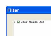
When you first open the Filter dialog, the Job name is displayed.
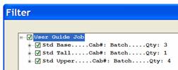
Click on the plus sign to expand the Job to show a list of cabinets that make up the Job.
Notice the green checkmark in front of each of the cabinets. This means that the cabinet is included in the nest.

Click on the plus sign in front of one of the cabinets to get a list of the parts that make up that cabinet. Again notice the green checkmark in front of each of the parts.
Again, this means that all these parts are included in the nest.

Here we have clicked on several checkboxes, changing them to a red X. The red X means that these parts will not be included in the nest.
Notice that we also clicked on a cabinet with qty 4. The red X means that this line item, all four cabinets and all parts for those cabinets will not be included in the nest.
Also notice the yellow exclamation point symbol in front of
Std Tall cabinet and in front of the Job name. This means that 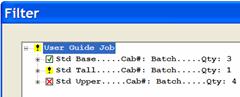 somewhere in the Job parts have
been filtered and somewhere in the Std Tall cabinet parts have been filtered.
When you can see all the parts it is not important but if you collapse the
presentation as shown, it indicates that somewhere in the list, parts are filtered
out.
somewhere in the Job parts have
been filtered and somewhere in the Std Tall cabinet parts have been filtered.
When you can see all the parts it is not important but if you collapse the
presentation as shown, it indicates that somewhere in the list, parts are filtered
out.
Let’s look at some places where this can be useful.
Let’s assume you have a standard job you run repeatedly, a dormitory layout perhaps. Perhaps on the new run you have a couple of cabinets left over.
Instead of changing the saved Job, you can simply filter out the cabinets, producing everything but those cabinets.
Another possible use would be to offer a method of using some larger pieces of scrap, or drops, when cutting parts manually. Instead of throwing this material away, you could find a few parts and manually nest them on the drop. Then filter them out of the Job, nest and run the rest of the parts.
It takes a little more work but does save material.
Now let’s go back and look at some additional output from the Nesting system.
When first run, the nest displays all the nests for the entire Job, color coded and three across. This gives you a general idea of the scope of the job as well as summary of material requirements.
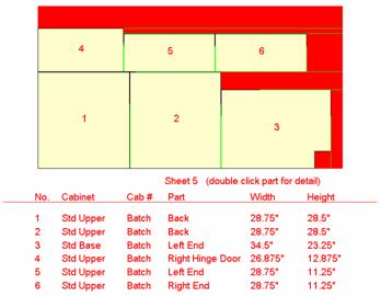
For a more detailed look at a single sheet, double click on it. You will then see a more detailed view of the sheet including dimensions as shown.
The text is shown in red because this display reacts to the Screen Shade slide control and if the background is black, black text would not show.
 You can now double click on any
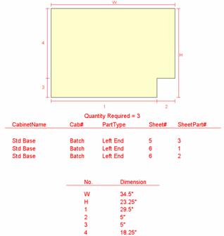
part on this screen to bring up a part display as shown.
You can now double click on any
part on this screen to bring up a part display as shown.
This display provides all the data needed to make the part.
To move back to the last screen press the Back button to the left. Note that the Back icon on the toolbar does not work in this are since this display is not HTML. The Back button, however, does the same thing.
At any time you can press the Reset View button and return to the top display page.
Now that the nest is complete, you can print drawings for the Job as well as labels for each part. Let’s start with drawings.
There are three selections for what you might want to print, View, Sheets or Job.
You select View you print a single sheet showing the view you currently see on the screen regardless of what it is.
Sheets print a page for each sheet of material showing the dimensioned sheet layout for each.
Job prints all the Sheets pages as well as a page for each distinct part in the Job. If two or more identical parts are needed, it only prints a single page for the part but indicates on the page how many of that part design are required.
The Print Labels button prints adhesive labels for every part in the Job. Currently the system is set up for printing labels designated as 5366.
These automated drawings and layouts are designed primarily
for in-house use. They require little effort to generate and contain all
required information but are likely not adequate for 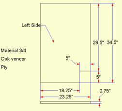 external use. If you need part
drawings for outside use, you may need to use the Line Drawing Editor to develop acceptable presentations as shown to
the left.
external use. If you need part
drawings for outside use, you may need to use the Line Drawing Editor to develop acceptable presentations as shown to
the left.
The nesting area, when combined with the Cut List, provides the primary manufacturing output from the software. It is intended that they contain enough information to machine and produce all the components required for the Job.