 These motions are important so you
should take some time and work with them until you are very familiar with their
operation. Before long these motions will become second nature.
These motions are important so you
should take some time and work with them until you are very familiar with their
operation. Before long these motions will become second nature.
This is the place where you develop and save your own cabinet and furniture designs. Some of the front end of this chapter is a repeat of information presented in the software overview. Please read through it again here. It is important that you understand these basics to make the software easy to both understand and use.
To create a library of your own designs, you start with a standard cabinet from a seed directory called “Standard Cabinets” and modify parameters until you fashion a cabinet designed the way you want. This new cabinet is saved under a new name in a new directory.
This cabinet can then be loaded, further modified and saved under yet another name.
This approach makes development of entire libraries easy and yet provides almost total flexibility.
The key ingredient to the eCabinet Systems approach, is the ability to display highly detailed, accurate graphic images of the cabinet. These images show exactly what the cabinet will look like using the current parameters. Changing a parameter causes the image to change, reflecting that change.
This image can be moved, rotated, exploded and zoomed. Components can be hidden, made transparent or turned into wireframe. In short, you can twist, turn, zoom and examine in minute detail the actual effect on the cabinet of any parameter changes.
This approach makes the adjustment process both easy and clear.
To develop a library, start with a standard cabinet. Change this cabinet to include all the parameters you want to be shared by every cabinet in your new library. Save this in a new directory as a “seed” cabinet.
Now, load this seed cabinet, resize and modify it to the first cabinet you want in your library. Save it. Load the seed cabinet again, create and save your next cabinet. In a short time you have an entire library of cabinets that all share the same characteristics as your seed cabinet.
Should you need to change any of these for a specific application, it is easy because the parameters reside with the cabinet, not the software. So, exactly how do we change the cabinet parameters?
We can separate changes to the cabinet into three categories, size, configuration and parameters.
Size is essentially height width and depth of the cabinet. This is changed on the Main page of the Cabinet/Assembly Editor but can also be changed whenever the cabinet is used in a job.
Configuration includes shelves, partitions, face frames, moldings, doors, drawer boxes, etc. The configuration of a cabinet is developed through a series of Editors that are reached from the Main page.
The Editors use the concept of Default components or settings. This means that many details such as door design, drawer front and drawer box design, pulls and moldings have a “Default” selection so that they do not need to be selected each time they are used. When one of these components is added to a cabinet, the current “Default Selection” is automatically used; therefore using a specific design is a two step process. First, the design is located and designated as the “Default” generally using a Set Default button. Then, Then the item is added which automatically uses the “Default” selection.
Parameters are the little bitty details concerning everything about the cabinet. Material, joinery, fits, insets, and about everything else. These parameters are adjusted in an area called Construction Settings that is also reached from the Main page or, they can generally be reached from any of the configuration Editors.
There are actually two kinds of parameters in Construction Settings, which can cause some confusion. Some parameters, a back inset for example, affect the cabinet as soon as they are changed. Other parameters define how items, a shelf for example, are added to the cabinet. Changing this type of parameter doesn’t change existing shelves, it only affects shelves that are added after the change. Of course, to make it even more confusing, if you highlight a shelf and then make a parameter change it changes the shelf that was highlighted.
You can tell what type of parameters you are adjusting by the title on the tab. If the word “Add” is in the title (eg. Add Shelf Settings), the changes will only affect newly added components. If the word “Add” is not in the title (Toe Kick, Back, Left End, etc) then any changes you make will immediately change the cabinet.
It’s actually pretty simple. Change size on the Main page or when you use the cabinet, change configuration using Editors and change parameters in Construction Settings.
Regardless of how many configurations and parameters the software allows for, cabinetmakers will always want to do something more. To address this, a Part Editor is available. Using the Part Editor, any part of the cabinet can be cut, pocketed, profiled or machined. This lets you create almost anything you can imagine. The amazing thing is that all of these creations can be actually machined on a Thermwood CNC router from the file created by the Part Editor. You can cut and profile individual cabinet parts pretty much any way you want.
If you want to put an edge profile on a part, you will need to develop a tool with the correct profile. This tool is developed in an area called a Shape Manager. Tools developed in the Shape Manager are used in the Part Editor to cut a profile on a part.
An interesting note about this feature is that once a profile is placed on a part in the Part Editor, that profile can be machined on a Thermwood CNC router even if a custom profile tool is not available. The Thermwood control can create a modeling program using a ball nose and corner bit to machine the edge using modeling techniques.
When you modify a part in the Part Editor, you should also define how the changes you made will react should the part size change. This is done through a Configuration Manager whose purpose is to define how modified parts in the Part Editor react to cabinet size changes.
So far it has been pretty simple but now we are going to add a valuable feature that can make it a bit more confusing if you don’t understand it. It has to do with the word “Assembly” in Cabinet/Assembly Editor.
A lot of complex cabinets and furniture cannot be defined with a single set of parameters. The approach eCabinet Systems uses to create these more complex pieces is to allow multiple cabinets to be loaded into the Cabinet/Assembly Editor at the same time and saved together as an “Assembly”. This approach is very powerful, but can be confusing. Let’s look at an example.
Suppose we need an upper island cabinet with a face frame and doors on both the front and back. We need to remove the back and put a face frame and doors on it.
In designing software to allow for this, you could create parameters for a face frame and doors on the back. But, there are thousands of these types of variations and you simply can’t make parameters for everything or the software would really get confusing. Instead, eCabinet Systems allows you to combine elements from two or more cabinets into an Assembly.
In this case, we take our first face frame cabinet and remove the back. Then we take a second copy of the cabinet (we can copy and paste it right there) and remove everything except the face frame and doors.
At this point the software sees two cabinets, one without a back and one without everything except the face frame and doors. Move the face frame and doors from the second cabinet to the back of the first cabinet and we have the assembly we want. It looks like a single cabinet with a face frame and doors on both ends but we know that, as far as the software is concerned, it is actually two cabinets, each with parts removed.
We can address and change the parameters of either cabinet by highlighting it and accessing Construction Settings.
In addition, other items can be loaded and included in either a cabinet or in the assembly.
Certain items that can be purchased through the program also have 3D images that can be loaded and added to either the cabinet or the assembly. This can get confusing because some of these items can be added to the cabinet in two different ways. For example, you can load a door pull as a Vendor Item and then locate it on a door. You can also load the same pull in the Door/Drawer Editor and locate it on the door. The difference in these two approaches is that when a pull is loaded in the Door/Drawer Editor, the software knows it is a door pull. When the cabinet size is changed, the location is automatically adjusted for the new size.
When the same door pull is loaded as a vendor item, the software does not know what it is. When the cabinet size changes, the location of the item does not change and is probably wrong at that time.
Other vendor items, a lazy Susan for example, does not have this conflict. The software doesn’t know what a lazy Susan is so adding it as a Vendor Item is the only way to display it. If you change the size of the cabinet, you will probably need to adjust the location.
A lot of items available through the program are in this category.
Another type of item that can be added to a cabinet or assembly is called a Display Object. These are item that you have a display file for but are not available from a vendor. These can be added to the cabinet although many times these types of items are added when a Custom Layout is developed. In general, if the item should appear each time the cabinet is used, a brass mounting foot for example, it should be part of the cabinet. If the item is sometimes, but not always, used with the cabinet it should be added in Custom Layout.
You can change the size of a Display Object by first highlighting it. Then you can either select Edit – Scale Selection from the top menu or right click and select Scale Object. This opens a scale dialog where you can adjust the size of the object.
This is a good time to discuss associations, cabinets and assemblies. This is another area that can be confusing if you don’t understand the underlying principles.
A “cabinet” is the smallest entity that can be saved.
A cabinet includes parts of the cabinet itself, but also includes any other items that are “associated” with it. An item that is associated with the cabinet is part of the cabinet. These associated items include Vendor Items, Display Objects, moldings, doors and drawers that are added directly rather then through the Editors, display cubes, panels and boards.
There are two ways to associate an item with a cabinet. First, if you highlight the cabinet and then load the item, the item is associated and is part of the highlighted cabinet. There is also a selection from the Right Click Menu that you use to associate and disassociate.
When a cabinet is saved as a cabinet, all items associated with it are also saved as part of the cabinet.
When you save an “assembly”, everything in the workspace is saved in their relative position to each other as an assembly file. This includes all the cabinets and all other items. To make it even more confusing, an assembly does not need to include a cabinet. You can load one or two display objects and save them as an assembly.
Moldings, doors and drawers and drawer boxes can be directly loaded as individual items rather than installing them through their Editors. This is like the “door pull” example we just covered. If the moldings, doors, drawer fronts and boxes are added through the appropriate Editor, the software knows what they are and makes appropriate adjustments when the cabinet size changes. If they are loaded directly, the software does not know what they are and makes no adjustments. Whatever is loaded remains the same and is unchanged even if the associated cabinet changes.
There are times when the ability to add these items without using the Editors is needed, which is why the capability is included in the software, however, normally these items are added in their individual Editors.
The final items that can be loaded are Display Cubes, Display Panels and Display Boards.
A Display Cube is strictly for display, but can be a powerful display tool. It is basically a cube, you determine the size, on which an image is placed. It has a wide variety of uses, although it tends to be used more in developing custom layouts than in the Cabinet/Assembly Editor. As an example, if you built a picture frame and wanted to put a picture in it, you could create a thin Display Cube and stretch a picture image over it and then locate the cube inside the frame. If you built a speaker box and need a cloth covering for the front, you could make the covering as a Display Cube. In Custom Layout a Display Cube can be used to simulate almost any appliance.
Display Cubes are even more useful because they can be taken to the Part Editor and their shape modified. In the end, however, they are simply tools used to display. Display Panels and Display Boards have one additional feature, they can actually be manufactured.
A Display Panel is a rectangular panel made from any sheet material in your library. You simply specify the size and material and then locate it as you want. Like the Display Cube, a Display Panel can be taken to the Part Editor and modified. The advantage the Display Panel has is that it is an actual part that shows up on the Cut List, nest diagrams, part drawings and CNC programs. A Display Panel can actually be manufacturered.
A Display Board works the same way but using board stock rather than sheet stock.
Now that we have examined the various items that can be loaded into the workspace, we should probably load something.
In almost every area of the software clicking the right mouse button brings up a menu. Items are loaded by right clicking and selecting Load Item. You can also click the load icon on the toolbar.
You can configure the workspace to suit your personal taste. Grids, axis lines and colors can be turned on and off. These are reached through a Grid Settings icon in the toolbar. Within the workspace is an Insert Target. This ball with axis lines protruding indicates where the next item will be loaded.
The Insert Target can be highlighted and moved so that one item is not loaded over or inside another. You highlight the Insert Target by double clicking on it, or if it is imbedded in an object it can be highlighted by pressing Ctrl + T.
The Insert Target is moved by holding the Ctrl key and using the Right Mouse Button.
Normally you don’t try to precisely locate an item using the Insert Target. Instead, it is used to keep items apart and then Align tools are used to quickly position items with respect to each other.
As you begin to load a cabinet you will notice that cabinets are divided into “types”. Base cabinets, upper cabinets, islands, tall, base corner, upper corner and detached toe are the cabinet types. With the exception of corner cabinets, the difference in cabinet type is not in the cabinets but in how the cabinet is handled when placed in a room in Custom Layout. With a few parameter changes, an upper cabinet can be turned into an exact copy of a base cabinet except it will be placed higher off the floor when added to a room. You could move it down in which case it would work just fine except, when all base cabinets are selected in some editing functions, the upper turned base will not be selected because it is not a “base” TYPE. A base cabinet can be turned into a detached toe. In fact, if you need a face frame, a base cabinet with a face frame can be turned into the face frame only by removing all the cabinet parts except for the face frame. The point of all this is that for all these different cabinets, you only have one set of settings and parameters to learn. They work for everything.
That being said, you should realize that you cannot change a cabinet’s type. Once it is an upper, it is always an upper even if it looks exactly like a base or toe kick. This means that it will initially be positioned a specified distance above the floor when placed in a room and will be selected whenever All Upper Cabinets are accessed
The starting cabinets in eCabinet Systems are called “Standard” cabinets and are located in the “Standard Cabinets” directory. There are separate cabinets for frame versus frameless to make it more convenient but realize you can change frame cabinets to frameless and back at will. The frame cabinets all have face frames, are made from material called “generic” and have slab doors and drawer fronts. Their actual configuration is not all that important because they will not work for any shop the way they are but simply offer a starting point. They also allow you to begin using cabinets in Custom Layout without having to develop your own library first.
The frameless standard cabinets are a stripped down minimum box without doors or shelves to which you add the components you will need. The frameless standard cabinets simply save you the effort of removing the doors, drawer, face frame and shelf from the frame cabinets.
The frame cabinets however, allow you to begin working with and learning other aspects of the software without having to develop a library of cabinets first.
The Standard Cabinets directory is used solely to hold the Standard cabinets. You cannot save cabinets in the Standard Cabinets directory. You must save them to a newly created directory. Also, it is recommended that you change the file names when you save them.
With a little forward planning, this approach can make development of entire libraries of cabinets easy. You need to start by analyzing the library of cabinets you need and considering shared features of the cabinets.
The first step is determining which characteristics are shared by the entire library of cabinets and modifying Standard cabinets to these characteristics. For example, all your cabinets may use ¾ inch sides of a specific material and a ¼ inch back. The back may full dado into the sides and they may all use blind dado construction.
The cabinets may use a specific door and drawer front design and specific hardware. You can set the door, drawer and hardware as Defaults although you do not want to put them on the cabinets at this time.
To begin, you may want to modify a base cabinet and an upper to these characteristics and save them as “seed” cabinets for this library. Now, You can use these “seed” cabinets to develop the individual cabinet designs needed for your library, knowing that you do not need to address all these settings and defaults for each individual cabinet.
This approach can be taken several levels deep. For example, after developing the initial “seed” cabinets, you may decide you need a subset of these for another application. For example, you may want some of these cabinets with a detached base. In this case, you can take the normal “seed” cabinet, modify it to a detached base cabinet and save it as a “detached base seed” cabinet. Now any cabinets you want to make with a detached base should start with the “detached base seed” cabinet.
The takes a little analyzing and planning but pays off in much faster and more consistent designs.
Let’s load a cabinet so we can examine some additional features. Right Click, select Load Item then click on Cabinets. Click on the Standard Cabinets directory. Note, you must click on the name itself, NOT the checkbox. This can be a bit confusing but the checkboxes are used to select items, or in this case directories that are then deleted by pressing the button at the bottom of the list.
Now click on Std Base Frameless and press OK. Again the checkbox is for deleting the item not selecting it.
You are now viewing the Main working screen of the Cabinet/Assembly Editor with a cabinet loaded. This screen is used for basic assembly tasks and for viewing the current state of the cabinet design.
Let’s look at some of the characteristics of this screen.
You are basically looking at a three dimensional workspace defined by three axes, X,Y and Z. The entire workspace is rotated by holding the Shift key and using the LEFT mouse button, it is panned using the Shift key and RIGHT mouse button and zoomed using Shift and BOTH mouse buttons.
These motions are important so you
should take some time and work with them until you are very familiar with their
operation. Before long these motions will become second nature.
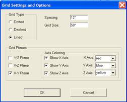
Display of the workspace can be customized using the Grid Settings icon. This opens the dialog shown.
A background grid can be displayed on each axis plane and the appearance of the grid is determined by the Grid Type setting.
The spacing of the grid elements can be set and, since we are working in an unlimited three-dimensional workspace, we also need to define the size of the grid. The number shown under Grid Size indicates the number of grid spaces on each side of each axis. For example if you set the Grid Spacing at 10” and set Grid Size at 10, you will have a grid that is 100 inches on each side of the axis or a grid that is 200 inches across.
At different times it may be useful to have the grid display on different planes. The planes on which a background grid displays is controlled in the Grid Planes area.
You can also decide which axes to display and the color to display it in.
A three dimensional Axis Designator icon is available at the lower left of the screen. This icon rotates with the workspace and is quite useful in determining which axis is which, when working with rotated assemblies. This Axis Designator color codes each axis with X being red, Y blue and Z yellow. It is recommended that you set the axis displays to these same colors to make the workspace more consistent and easier to understand.
There is also an Insert Target which we have already discussed. It initially appears at the origin where the axes intersect. This target determines the location where an item, such as a cabinet, is inserted into the workspace when it is loaded. This Insert Target can be moved by first highlighting it by double clicking on it and then while holding the Ctrl key, using the right mouse button. If it is hidden inside a cabinet, you can also highlight it by pressing Ctrl and T.
In addition to moving the entire workspace, you can also move and rotate items within the workspace. An item (cabinet, display part, etc) is moved by highlighting it and then holding the Ctrl key while using the Right Mouse Button.
This may be a good time to introduce another feature of the workspace, the C-Plane. When you first enter the Cabinet/Assembly Editor, you are looking directly at the XY Plane with the X Axis defining left and right movement and the Y Axis defining up and down motion. The C-Plane is also set to the XY Plane called C-Plane Front. This means left and right movement of the mouse moves items along the X Axis and up and down movement of the mouse moves items along the Y Axis, or mouse movements correspond to a front view.
Since you can rotate the entire workspace, should you rotate the workspace so that you are viewing the left side, left to right movement of the mouse still moves along the X Axis but now that means front to back movement on the display.
To get left and right mouse movement to move items left and right in this new orientation, the C-Plane needs to be changed to C-Plane Left. This is even more important at random rotation angles.
Note that you can change viewing orientation using the arrow keys, left, right, top and bottom. The Home key is the front view and the End key is the back view. When you use these keys to change viewing orientation, the C-Plane also changes to the corresponding orientation automatically. When working at intermediate angles, you can change the C-Plane manually.
As a note, there is a rotate dialog that is used to rotate items within the workspace. There is more information on moving and aligning items in the section titled “Moving and Aligning Items in the Workspace”.
From this position we can start to modify the cabinet. As stated earlier, these modifications are three types, size, configuration and parameters. We will start by changing size although, most of the time size changes are done as part of adding the cabinet to a job.
To change size, input a new size in either Width, Height or Depth and press Enter. The cabinet will change to reflect the new size. Should you ever try to create a size that isn’t workable, the system will catch the error, alert you and restore the previous size.