The Display Part Editor is an area of the software that offers a powerful graphics tools used to add color and texture to three-dimensional objects which can then be used in the Cabinet/Assembly Editor or in Custom Layout.
This process starts with a three-dimensional graphics file that is generated by a third-party software program. The file must be in the .stl or .hsf file format. Many three-dimensional CAD packages can output .stl files. In addition, several web sites provide .stl files for download. Some of these sites charge for downloads and others are free.
The eCabinet Systems web site also has an area where Members post three-dimensional files. Some of these are .stl and others are .hsf, already fully rendered and ready to use.
In addition, in the directory ecabinets/sample_STLs you will find some .stl files that you can process through the Display Part Editor.
Finally, any part in the Cabinet/Assembly Editor or Custom Layout can be exported in the .hsf format and loaded into the Display Part Editor. These can then be textured and saved as .hsf where they can then be used as Display Objects in the Cabinet/Assembly Editor or Custom Layout.
You can export an item, display part or part of a cabinet in the .stl format from the Cabinet/Assembly Editor and then load it into the Display Part Editor where appearance and texture can be added or adjusted. This is especially important for some parts that are modified in the Part Editor. Cabinet parts automatically receive a texture using standard settings. When a part is modified, many times the texture settings do not produce an acceptable appearance. Exporting these parts and then texturing them using the Display Part Editor is a way to improve the appearance.
There is a downside to this, however. When a cabinet part is exported and textured in the Display Part Editor, it is saved as an .hsf file. It is then loaded back into the Cabinet/Assembly Editor as a display part. At this point it is no longer a cabinet part, it is a display part. It will not be included with the cabinet parts in the Cut List and will not be nested with other cabinet parts.
We will describe the operation of this area by creating some examples. You can work along with these examples using your system.
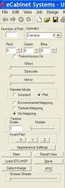
Bring up the Display Part Editor using the icon located in the toolbar at the top.
We will use one of the .stl files from the sample_STLs directory for our example here. We will show how the item changes appearance as various settings are adjusted.
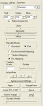
Controls available in the Display Part Editor are shown to the left.
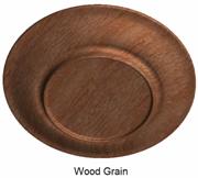
Start by pressing the Load STL/HSF button. We will select the file Sample_Plate1.STL.
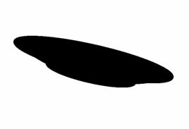
The work area in the Display Part Editor is oriented the same as the Overhead view in Custom Layout. When the image first loads, it is oriented as it would appear in the Overhead view in a Custom Layout and is pure black. It can be manipulated using the standard mouse controls and after rotating looks something like this.
We will start by changing color. The Red, Green and Blue at the top control the color of the item. Each can be adjusted from zero to 255. Change the Red to 255 and you get the following:
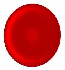
If you look at the image carefully, you will see that it does not look particularly smooth but has ridges and color variations.
If you look at the controls you will see that Flat is checked as the Render Mode. Change this to Gouraud.
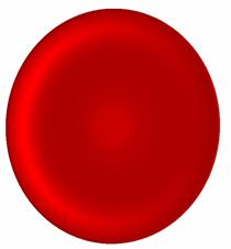
This result is much smoother and more realistic. This might be just the opposite for a flatter part. As a general rule, try both Flat and Gouraud and use the setting that gives the best overall appearance.
 Change the Blue Setting from zero
to 255.
Change the Blue Setting from zero
to 255.
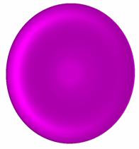
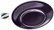
The plate is now a purple or magenta color.
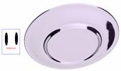
Changing the Green setting to 255 results in a pure white color. 0,0,0 is a black, 255,255,255 is pure white. Numbers between these can create 24 million different colors.
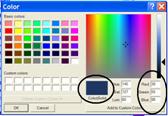
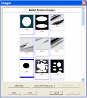
In trying to determine a color, you can turn to a typical color definition dialog. These can be found in a variety of formats in a lot of different software. You can access one right from this area by pressing the Select Image button and then selecting Add Custom Solid Color and then selecting Define Custom Color>>. Work with the mouse to develop the color you want and then copy the Red, Green and Blue settings for that color into the Display Part Editor.
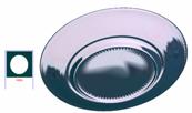
We have changed the color to a blue and will now show you how the Gloss and Specular controls function.

Here is the plate with both Gloss and Specular set to minimum. It appears flat with few highlights.
Increasing the Specular increases the effect of the color and adds a three-dimensional aspect to the image.
Now, increasing the Gloss makes the surface shinier. Gloss and Specular interact in determining the appearance and you will need to experiment with the settings to get the appearance you actually want.
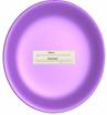
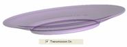 Checking Transmission On makes the image transparent, like it was made of
glass.
Checking Transmission On makes the image transparent, like it was made of
glass.
The darker and more intense the color, the more opaque the appearance. A pure white color results in an almost perfectly clear glass look.
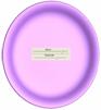
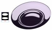
Both Gloss and Specular still function with Transmission On. High Specular and Gloss result in a clear glass look with a shiny surface. Low Gloss and Specular result in a product that is transparent but with a flat less reflective surface.
The Gloss control makes the surface shiny or reflective. In the real world, as a surface becomes more reflective, it begins to reflect its environment. A mirror is a good example of this.
To simulate this, the Display Part Editor uses a selection called Environmental Mapping. Before this works, you must select an image to reflect. This is done by pressing the Select Image button. Within the selections is a directory called Reflections. This contains images that result in various shiny appearances. These images look a little strange but do create some really nice appearances.
As a general rule, the sharper and more abrupt the contrast between colors the more reflective the surface will appear. As the boundary between colors becomes more gradual, the surface it reflects from will appear less reflective and shiny.
The Mirror control adjusts the brightness of the reflected image, changing the appearance. To the left it becomes less shinny and uses the color set above. As it is moved to the right, it becomes more reflective and takes on more of the color of the image being reflected. You may want to try several of these images and work with the Mirror control to get a feel for the effects you get. Following are some composite images showing the image used and the effect on our plate.
Another way to use an image is to map the image to the surface of the part. Select an image and then select Texture Mapping. There are two additional controls that affect how the selected image or texture is mapped to the surface of the object. The first is Texture Scale and it determines the size of the texture image with respect to the size of the object itself. Increasing the number increases the size of the texture image. The second control rotates the image with respect to the object. Using these is a trial and error process. Rotate the image to achieve the best overall appearance. Here are some images mapped to our plate.
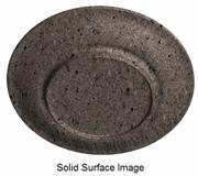
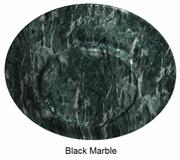
As you can see, the variety of appearances possible is virtually unlimited. You can even use flowered wallpaper to create flower patterns on the plate.
Using the tools just shown, a single object can be colored and textured and given almost any surface appearance. Some items, however, are comprised of two or more components each with a different appearance. It is possible to duplicate these items by loading more than one .stl file and then locating and texturing them individually. They can then be saved as a single .hsf display part.
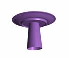
To demonstrate this we will load another .stl file from the same directory. This time we will use a glass represented by the file sample_glass1.stl. Here you see the original plate and the glass we just loaded. You will notice that the glass is oriented upside down and under the plate. This most likely means that the coordinate system that the glass was created in is oriented differently than the coordinate system that the plate was created in. This is a common occurrence, especially when using files from different sources. The Display Part Editor provides controls that let you invert various axes as needed to match coordinate systems.
It is not absolutely necessary to match coordinate systems, however, if you don’t, objects will rotate and move in the wrong direction when you try to manipulate them. In this case, we will reverse all the axes since not only is the Z axis backward but the glass moves in the wrong direction when you try to move it.
The buttons under Invert Part invert the various axes by depressing them. As you see, the glass has moved to the top side of the plate. We have made the plate transparent to show that it is not, however sitting on the plate but is suspended above it.
It is possible to move or rotate the plate and, in fact it is possible to modify the appearance of either of the two objects individually. Notice at the top that the Number of Part display now reads 0. This is the first part loaded, in this case the plate. Any changes made will apply to just the plate. To select the glass, RIGHT click on it and the Number of Part will read 1. You can now make changes to the glass. Moving parts, however, gets a little more involved.
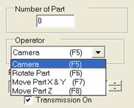 If you look at the top of the
control column you will see an area called Operator.
In this area are four selections. The selection determines what moves when you
use the mouse controls.
If you look at the top of the
control column you will see an area called Operator.
In this area are four selections. The selection determines what moves when you
use the mouse controls.
The first is called Camera. When this is selected, everything moves. It is called Camera because it is very much like having a fixed scene and simply moving the camera to view the fixed scene from different directions and orientations. In Camera, the scene doesn’t change, only your view of the scene changes.
This is actually fairly important because the orientation of the object with respect to the real world, the scene, is the orientation the object will be in when it is placed in a room. If you actually rotated the glass on its side in the real world, when you placed it in a room it would be lying on its side.
The next three selections actually move or re-orient the
active object. If you select Rotate Part,
the active part will rotate with respect to all other parts and with respect to
the real world. To the left you can see what 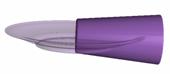 happens when we use the Rotate Part function on the glass, which
is part 1. You need to hold down the Shift
key while using the right mouse button to rotate or move a part.
happens when we use the Rotate Part function on the glass, which
is part 1. You need to hold down the Shift
key while using the right mouse button to rotate or move a part.
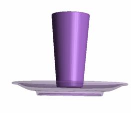
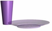 Here we see our plate and glass
positioned next to each other and at a common height as it might be used as a
place setting. Doing this required switching between Move Part X&Y and Move
Part Z to position the glass next to the plate and adjust the height. It
also required us to switch back to the Camera
view several times to evaluate how we were doing. Take some time and play with
the controls to get familiar with the various operators.
Here we see our plate and glass
positioned next to each other and at a common height as it might be used as a
place setting. Doing this required switching between Move Part X&Y and Move
Part Z to position the glass next to the plate and adjust the height. It
also required us to switch back to the Camera
view several times to evaluate how we were doing. Take some time and play with
the controls to get familiar with the various operators.
Once the object or objects are complete, you can save them as an .hsf file that can be used by the program. You can specify a directory name and file name. They are saved with your directory becoming a sub-directory of the ecabinets directory because that is where the system looks when placing a Display Object. You can also input a cost for this item and indicate that you want it added to the Cut List. Then, when you add the object to a Job, it is also added to the Cut List and its cost is added to Material Cost.
Developing a pleasing appearance for an object can take some time and effort so, once you develop one that you like, you can save the appearance settings by pressing the Appearance Settings button. From this dialog you can save the current setting, load previously saved settings or delete settings you may have saved in the past. There are several saved appearances already available in this area that you might want to experiment with.