The Hardware Hole Editor is an area of the software used to create a mounting hole pattern that is then associated with a piece of hardware. When that hardware is used on a cabinet, the hole pattern is automatically added to the appropriate parts.
Most hardware offered in the eCabinet Systems program already has a hole pattern associated with it. If that hole pattern is acceptable, you need do nothing else. If not, this editor can be used to either create a new pattern or modify the one that currently exists.
The basic approach is to define a geometric hole pattern, save the pattern and then associate it with one or more components. When these components are used on a cabinet, the associated hole pattern is automatically added to the appropriate cabinet parts.
If your parts are to be processed on a CNC router these hole definitions are important because they will be machined into each component. This saves substantial time, allowing hardware components to be mounted to cabinet panels prior to assembly.
The key to using this area is understanding the basic concept behind the layout of the hardware hole patterns.
The single most important point to understand is that the way a hole pattern is defined is different for different types of hardware. The way the pattern is defined depends on the type of hardware the pattern is for. Although the workspace is the same, the procedure is different for different types of hardware. Once you understand this, creating the pattern is fairly easy.
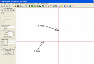
The workspace is a CAD type drawing area bisected by an X and Y Axis. The X and Y Axes are a key to understanding how to develop the hole pattern. The significance changes for the X and Y Axis, based on the type of hardware that the hole pattern is for. For example, for a door hinge, the Y Axis separates holes that are drilled into the cabinet side (those to the right of the Y Axis) from the holes that are drilled in the back of the door (holes to the left of the Y axis). The same Y Axis functions differently when used to define holes for KD/RTA fasteners. Holes to the right of the Y Axis are cut into the edge of one panel and holes to the left of the Y Axis are machined into the face of the mating panel. The Area Overview for this area details the way hole patterns must be located for each type of hardware. You should print out this information and the diagrams and use these for developing hole patterns.
The X Axis is also significant because it defines how the hole pattern is located along the edge. For example, when specifying hinge location for a door, you specify a distance that the hinge is located from the door edge. What you are really specifying is the location of the X Axis in the hole pattern for the hinge. If you locate the holes so the X Axis is in the center of the hinge, you are then locating the center of the hinge.
Understanding Depth is also important. As a general rule, a Minus depth in cut into the cabinet component. The dimension is measured from the surface of the part, so a minus ½ inch depth is drilled one half inch into the part.
Plus depth is primarily used for locating drill holes into a drawer body. On a drawer slide, a minus ½ inch depth and a plus ¼ inch depth for a single location will drill a hole ½ inch deep into the side of the cabinet and will drill a second hole in the same location ¼ inch deep into the drawer body.
Note that even though the drawer body and cabinet side are separated by the thickness of the drawer slide, the hole depth for both parts is measured from the surface of the part and not from a common center point, even though that is how they are displayed.
To demonstrate, we will develop a hole pattern for a hinge and drawer slide. The process for other components is similar.
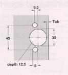
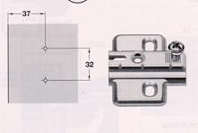
Above are diagrams similar to those found in hardware catalogs that define the required hole pattern for a component. The diagram to the left is a machining pattern required to attach the hinge to the door and the pattern to the right shows the mounting holes that must be drilled into the cabinet side.
For the particular hinge and overlay we are using, the Tab dimension above is 3mm.
Start by setting up the editor for this task. Since the dimensions in our drawing are in millimeters, go to Settings/Preferences and change Dimension Display to Metric.
Next, since some dimensions are in half millimeters, we will set the Grid to 1mm and the Snap to .5mm. Next, use the plus key to zoom to a comfortable working height.
Start by defining the 35mm hole. The right hand vertical edge of the door is the Y Axis on the drawing. The center of the hole is half of 35, or 17.5mm plus the Tab which is 3mm for a total of 20.5mm.
Set the hole depth, in this case -12.5mm. Then locate the three holes. The result looks like this.

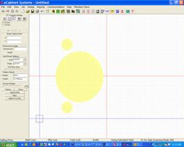
You can view the pattern we just developed in 3D by pressing the View button and using the mouse controls to move and rotate it as shown to the right.
Now let’s place the holes for the mounting plate. These holes are placed to the right of the Y Axis. Leave the hole depth at 12.5mm and locate two holes 37mm from the edge and 32mm apart. In 3D, the final hole pattern looks like this.
Now that this hole pattern is complete, we save it under a name. Then we will associate it to the actual hinge and mounting plate we plan to use. Press Attach to Part and select the type of part and the vendor. Then, select the actual piece and associate it to the hole pattern.
Note that if you are using a hinge and separate mounting plate, you have the choice of creating a hole pattern for the hinge and mounting plate combination and associating it to the hinge or, creating a separate pattern for the hinge and the mounting plate and associating one pattern to each component. If you always use a particular combination you can use a single pattern. If you mix hinges and mounting plates you should probably create a separate pattern for each.
Next, we will develop a mounting hole pattern for a drawer slide. Start with a diagram of the slide that shows mounting hole locations for both the cabinet side as well as the drawer box.
This is a little different than the hinge since all holes are located to the right of the Y Axis.
Holes with a Minus depth are put into the cabinet side and holes with a Plus depth are drilled into the drawer box.
We will start by locating the holes in the cabinet side. Set the minus hole depth and locate the required holes. In 3D, the resulting pattern looks like this.
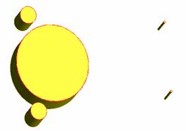
Now we are going to define holes in the same location but this time they will be in the Plus direction and only half the depth. We have also added two additional holes in the positive direction for illustration. The 3D view of these is:
You will notice a small red area on each hole. This separates the holes that extend above, which are the ones that go into the drawer box, from the holes that extend downward, which go into the cabinet side. In actual operation the holes that extend in both directions can be placed at one time by specifying both a Plus and a Minus direction.
This gives you an overview of the operation of this area. Other types of hardware use the X and Y Axes in somewhat different manners, but the basic principles are the same.