Using the Line Drawing Editor
The Line Drawing
Editor is used to develop traditional line drawings of different aspects of
the job. It offers computer assisted tools that make the process fairly quick
and easy.
The process starts by sending a cabinet, group of cabinets
or assembly from the Cabinet/Assembly
Editor or sending a cabinet, group of cabinets, wall or entire room from Custom Layout to the Line Drawing Editor. There, items are
rotated and positioned, copied and pasted between pages to obtain the basic
drawing layout and then dimensions and notes are added.
The key ingredient in the Line Drawing Editor is a concept called a Line Drawing Object. A Line
Drawing Object is essentially a three-dimensional line drawing, geometric
representation of parts, cabinets, walls and complete custom layouts. The Line Drawing Object contains every bit
of geometric data about the object.
Although the Line
Drawing Object is a full three-dimensional representation of the object, a
cabinet for example, you cannot access all the information at once. From a
front view, it appears to be a two-dimensional line drawing of the cabinet
front and all dimensions for the front area available. Data for the back is not
available from the front view, however. To get data for the back, you need to
rotate the Line Drawing Object of the
cabinet until you have a back view. Now, the same object looks like a line
drawing of the back of the cabinet. Turn it to the side and you have what
appears to be a two-dimensional drawing of the side. Turn the Line Drawing Object to an angle and you
have what appears to be an isometric drawing of the cabinet.
This simple concept is rather important because it forms the
basis for the entire Line Drawing Editor.
To understand how this is used, letís look at a cabinet
drawing. A common drawing is a front, side and top view of a cabinet. Typically
this requires three two-dimensional line drawings, one for the front, one for
the side and one for the top. In the Line
Drawing Editor it requires three copies of the Line Drawing Object for the cabinet. One is turned to the front
where it looks like a two-dimensional front view, one is turned to the top
where it appears to be a two dimensional drawing of the top and the third is
turned toward the side where it appears to be a two-dimensional view of the
side.
It appears to be three separate line drawings but it is
actually three identical three-dimensional Line
Drawing Objects each turned a different direction.
The process for creating this is straightforward. The
original Line Drawing Object of the
cabinet is copied and pasted twice resulting in three complete copies of the
cabinet. One drawing is turned to the side, a second is turned to the top. The
drawings are then moved to the proper position relative to each other and
dimensions are added.
There are four types of Line
Drawing Objects, Parts, Cabinets,
Walls and Rooms. Some objects are
contained inside others. For example letís consider a wall populated with
cabinets. You can copy and paste the entire wall, but you can also copy and
paste any of the cabinets on the wall. You can also copy and paste any
individual part of any cabinet on the wall. In the same manner, you can copy
any wall from a room, any cabinet from that wall and any part from that
cabinet.
You should begin to see the incredible power and flexibility
in this approach. The flexibility gets ever greater when you consider some of
the options available when selecting Line
Drawing Objects to send to the Line
Drawing Editor.
There are two sources for Line Drawing Objects, the Cabinet/Assembly
Editor and Custom Layout. The Cabinet/Assembly Editor sends the Line Drawing Objects s that are
highlighted. From Custom Layout, you
can also select what you want to send. You can send the entire Job, a single
wall with all associated items or, you can specifically select the items you
want to send. When you do this they show up in the drawing in the correct
dimensional relationship to each other.
You should recognize that when you send an entire layout as
a Line Drawing Object, you are
dealing with a lot of data so system response will be slower than if you work
with a wall or a single cabinet. This means that you should try to work with
the smallest object possible to achieve your goal, rather than send an entire
layout and then copy a single cabinet to make a drawing.
Because of the high level of flexibility in selecting
objects, you need to tell the system what type of object you are looking for.
You do this by selecting one of the first four icons on the toolbar. They are Cabinet, Part, Wall and Room. If you select Cabinet complete cabinets highlight when you pass over them, if you
select Part then individual cabinet
parts highlight and can be selected. You cannot select a cabinet in the Part mode. You cannot select a part in
the Cabinet mode. You can only select
the type of object that is currently active, based on your toolbar selection.
One additional note, although the icon says Room it actually means the entire Custom Layout. If you have a layout that
includes several rooms, they are all treated as a single room and are all
selected when the Room icon is
active.
You can highlight multiple objects by holding the Ctrl key while selecting. Therefore, if
you want one room from a multi-room layout, you can switch to Wall select the walls that make up the
room you want and send them. You now have a Line
Drawing Object for the one room.
When you pass the cursor over an item, it will turn magenta
color. This does not mean it is selected but does indicate what the system
sees. If you click when a part is magenta it turns green which indicate that it
is selected and can be copied, pasted, rotated and moved. If you click on a
green highlighted part, it is de-selected.
You can move and rotate only parts that are independent Line Drawing Objects. If the selected
object is part of another object, it cannot be moved or rotated independently.
You cannot disassemble a Line Drawing
Object. If a cabinet is part of a wall, you cannot move or rotate it by
itself. You must copy it and paste it as an independent object. Then it can be
moved and rotated. The same thing applies to parts on a cabinet. You cannot
move a door away from a cabinet. You can, however, highlight the door, copy it and
paste it somewhere else on the drawing or on another page where it can be moved
and rotated at will.
This brings up another potential problem. What if the part
you want to highlight is hidden by another part, or perhaps it is inside the
cabinet. The system offers a Hide
command that lets you hide a selected object so you can access objects behind
it. When the object you want to hide is magenta, click on it. This will green
highlight it. Right click to bring up the Right
Click Menu. Select Hide and the object
will disappear offering access to objects behind it.
The Esc key
deselects everything.
The Line Drawing
Editor supports multiple pages. Each page is a separate drawing. Objects
can be copied and pasted between pages. Each time you send a Line Drawing Object to the Line Drawing Editor it is placed on a
new page. You can also create a blank new page using the Add Page icon. You can also rename the pages to anything you want.
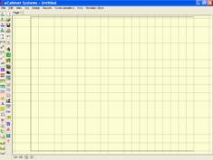 The page size is automatically set
to the active page size of the current default printer on your computer. If you
want a different page size, set the desired page size in the File Ė Print area. Select the printer or
plotter you want to use and select the proper page size before accessing the Line Drawing Editor.
Once the printer and page size are properly set, letís set
up the page area. Go to the Line Drawing
Editor. There are two ways to access function here. You can use the various
icons from the toolbar located across the top of the drawing page, just under
the system toolbar. The same functions can also be accessed using the Right Click Menu.
By the way, the toolbars are standard windows toolbars so
they can be relocated to the sides, bottom or anyplace else you like. An
example of an alternate layout is shown here.
We will use the default layout in this guide.
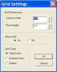
Next, we will set the grid. Press the Grid icon and the dialog to the left appears. Grid dimensions are
the actual measurements on the drawing page itself. You can turn the background
grid on and off and, as with the other grids, there is a choice of three types
of grid to display.
We will set the parameters to a half inch by half inch,
solid line grid. Press OK
Next, we will select the font for the text on our drawing. There
is a Font icon on the toolbar that
can be used to access this function or you can right click and select Font.
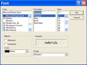
The dialog to the left appears. We will use Microsoft Sans Serf in Regular form, 11 point size and black
color. We will be able to change specific text on our drawing if needed by
highlighting the text we want to change and either pressing the Font icon or using the Right Click Menu as we just did here.
Changes are applied to new text and any text that is highlighted when the OK button is pressed.
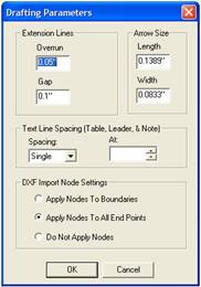 The next area to define is called Drafting Parameters. It is accessed
either through the icon at the top or by right clicking and selecting Drafting Parameters.
This area defines three functions. The first is the
appearance of Extension Lines. Extension Lines are the lines that run
from the object to the dimension line.
 Overrun
is how far the extension line extends past the dimension line. All measurements
here are based on the printed page. If you set Overrun to ľĒ, the line will extend past the dimension line ľĒ as
measured on the final printed page.
The Gap specifies
how far away from the node being measured before the extension line starts.
The next part of Drafting
Parameters determines the line-to-line spacing of text. This affects text
in each area including Notes, Leaders
and Tables.
All the settings in Drafting
Parameters will be used on new items placed on the drawing.
Changes to these parameters also affect any items that were
highlighted when the change was made. If you highlight a dimension line and
change the Gap or Overrun, the gap and overrun of the
highlighted line will change. If you highlight existing text on the drawing and
change the Text Line Spacing the
line-to-line spacing of the highlighted text will change.
Changes do not affect existing items that are not
highlighted.
The final area of Drafting
Parameters concerns loading DXF files into the drawing and is covered in
the section titled Loading and
Dimensioning DXF Drawing Files.†
The final item in setting up the drawing page is the Edit Move Increment. This is the
distance items move, as measured on the page, when the arrow keys are used.
Select the Edit Move
Increment icon to bring up the dialog. We will set it to .125 inch for this
demonstration.
Now that the drawing area is set up, Let us create a
standard front, side and top view of a three drawer base cabinet.
From the Cabinet/Assembly
Editor we will load a base cabinet and then press the Line Drawing Icon.
From the dialog, select Take
Cabinet.
This sends us to the Line
Drawing Editor and takes the currently displayed cabinet with us.
The cabinet appears on a new page.
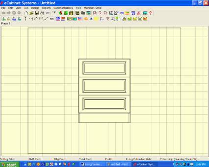
The cabinet appears too large and there is a temptation to
zoom it down in size before you copy and paste it. Donít do it. When you copy
and paste an image, the pasted image will be full size, regardless of the size
of the image you copied. At that point it will be almost impossible to zoom the
copies to the same scale as the original.
Instead, copy and paste all images you want even if they
donít fit properly and then select and zoom down everything at once. This way
you know that all the images are at the same scale.
Set the select mode to Cabinet
by clicking the Cab icon on the
toolbar or by right clicking and selecting Select
Mode Ė Cabinet.
Move the cursor over the cabinet, when it turns magenta
click on the cabinet to highlight it.
Copy it by holding the Ctrl
key and pressing C on the keyboard.
Now, you must move the original out of the way so you can
paste a copy. While it is still highlighted, press and hold the Shift key and move the cabinet using the
right mouse button.
Now paste a new copy by holding the Ctrl key and pressing V.
Press Esc to
remove highlights from all items. Otherwise, if you try to move one you will
move them all because they are all highlighted. You can now move the new copy
out of the way so you can paste yet another copy.
You should now have three copies of the cabinet.
Highlight all three and zoom them down to a smaller size.
Hold the Shift key and zoom using
both mouse buttons. You now have three identical drawings of the front of the
cabinet.
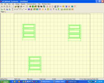
This might be a good time to note that you can highlight any
items on the screen by clicking on them, or, if you click and hold the left
mouse button you can pull a green rectangle over the items you want to
highlight. Any item that the green rectangle touches is highlighted.
Press Esc to
deselect everything.
Select and move one cabinet at a time by highlighting it,
holding the Shift key and using the
right mouse button, until they are positioned properly with respect to each
other.
Now, highlight one of the cabinets. Then right click to
bring up the Right Click Menu.
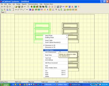
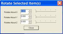 Select Rotate Dialog and a dialog screen appears that you can use to
rotate the highlighted cabinet.
Turn one cabinet 90 degrees on the Y Axis and one cabinet 90
Degrees on the X Axis. The result is a standard front, side and top view
drawing.
Now we will add dimensions to our drawing.
The Line Drawing
Objects that make up our drawings are full geometric representations of the
original items. This means that the relative position of everything on the
object is known accurately. This means that you will not need to know any
dimension number, but instead every dimension is developed by simply letting the
system know what you want to measure.
We specify what we want to measure by clicking on nodes.
A node is the intersection of any two lines or the center of
hole. Press M to see all available
nodes on the page.
Because of the total flexibility, we can dimension almost
anything. In two dimensions we can dimension the horizontal or vertical
distance between two nodes. We can also dimension the diagonal distance between
two nodes. We can also dimension in three dimensions. This is useful for
dimensioning isometric orientations of the Line
Drawing Object.
We will start by looking at two-dimensional (2D)
dimensioning on our current drawing and then examine dimensioning in 3D.
Because of the variety of dimensions we can develop, we need
to tell the system what kind of dimension we are trying to develop. We do this
by setting a drafting mode.
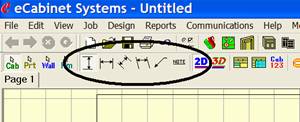
If you look to the left of the drawing toolbar you will see
a set of icon selections where we will indicate the drafting mode we want to
use.
The first two specify we want the vertical or horizontal
distance between the two nodes we select. These two modes are interconnected so
that should you select two nodes whose dimension in the selected direction is
zero, it automatically switches to the other mode. For example, should you set
the Vertical Mode and then select two
nodes, say the two top corners of a cabinet where the vertical dimension is
zero, the system automatically switches to the Horizontal Mode and displays the width of the cabinet.
Since there is no practical reason to ever display a zero
dimension between two points, this automatic switching saves a lot of time when
developing horizontal and vertical dimensions.
Should you ever need to display a zero dimension, you can
use the Note feature which will
result in the same presentation. Now letís look at the creation of some
dimensions.
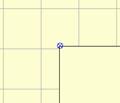
Start by making certain that the 2D icon is selected on the toolbar. Now move the cursor over the
various nodes on the cabinet. When you pass the cursor over a node, it
highlights as shown to the left.

 Now, click on a node and move the
cursor away. A dimension line attached to the node follows the cursor.
 Highlight and click on a second
node and a dynamic dimension line appears. Now, the dimension text follows the
cursor. You move this into position and click again to anchor it.
You can leave the dimension between the extension lines or
you can move it outside the lines as shown to the left.
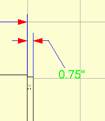
This is useful when dimensioning nodes that are too close
together to fit the dimension text as shown. Once the dimension text is placed,
the actual text itself can be moved on a pivot line by highlighting the text as
shown and, while holding the Shift
key moving it using the left mouse button.
 Actually, every aspect of the
dimension and text position, other than the nodes that define it, can be
repositioned after it has been placed. There are two things you might want to
change on a dimension, the position of the text or the position of the
dimension line itself.
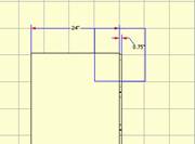
Here the 24Ē dimension text is highlighted. It can now be
moved left and right along the dimension line.

Here the text and the dimension lines are both highlighted.
Now, the distance of the dimension line from the cabinet as well as the
position of the text can be adjusted.
You can delete a dimension by highlighting either the text
or the text and lines and pressing Delete.
Should you delete a dimension by mistake, the Undo icon or Ctrl Z
restores it.
 At times there are a lot of nodes
concentrated in an area making it is difficult to select the exact node you
want. When this occurs, you can easily zoom in and out during the dimensioning
process.
Hold the Ctrl key
and pull a rectangle. This time the rectangle is blue instead of red. When you
release the mouse button, the screen zooms to the area defined by the blue
rectangle.
Here, the entire display has been zoomed to the area defined
by the blue rectangle.
Press the Home key
to return to a full view of the drawing.
After pressing Home,
you can press the End key to return
to this zoomed view. Now, letís look at defining a dimension using the zoom
functions.
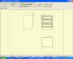 From this full view of the drawing
page, we will place a dimension line showing the width of the top drawer in the
drawer stack from the front view.
If you look carefully, you will see that there are a lot of
nodes around each upper corner. It would be all but impossible to select the
proper nodes without the zoom functions.
Notice that a blue zoom rectangle has been pulled over the
upper left corner of the cabinet.
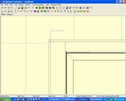
When the mouse button is released, it is easy to locate and
click on the corner of the drawer front as shown.
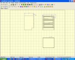
Once the first point of the dimension lines has been
established, press Home and the display
returns to a full view of the drawing page.
From the full view and while dragging the dimension line,
pull a zoom rectangle over the right corner.
Again, when you release the mouse button, the view zooms to
the area defined by the blue zoom rectangle.
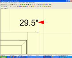
Again, it is easy to locate and click on the second corner
of the drawer front.
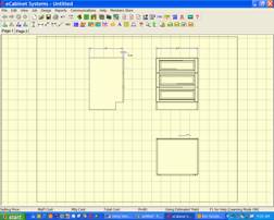
Now the dimension line has been established, again press the
Home key to zoom back to full view of
the drawing page.
From the full view, you can locate and lock the dimension
line and text.
This overall technique is critical to making the
dimensioning process easy and accurate. It is actually fairly easy to do and
should quickly become second nature with a little practice.
Letís take a closer look at the extension line and some
special dimensioning techniques.
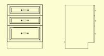
Here is a front and side view of a cabinet.
We want to create extension lines between the cabinets and
dimension the height.
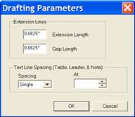
To do this we need to
reset our Drafting Parameters.
We will use these settings to place a dimension line between
the cabinets.
Set the Gap to 1/8
inch and set the Overrun to 1.5 inch.
Now place the dimension.
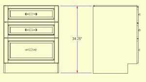
As you can see, we use the Overrun to extend the extension line from the dimension line to the
cabinet on the right.
Changes to Drafting
Parameters affect new dimensions that are placed as well as any dimensions
that were highlighted when the change was made.
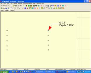
Next, we will examine how holes are dimensioned.
Shown here is a zoomed image of the inside surface of a
cabinet side showing the holes for an adjustable shelf.
Notice that when you place the cursor over the center of a
hole, it highlights like a node.
If you click on it and move away, the dimensions of the hole
are displayed as shown.
Again, you can position and anchor the text anyplace you
want.
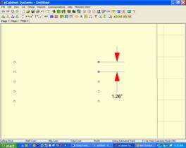
If instead of placing the text, you highlight another node,
either another hole as shown here, or any other node, and then click on it, a
standard dimension display is created between the nodes.
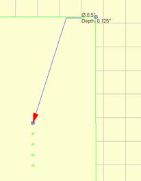
Now, letís look at how we create a dimension line between
the row of holes and the edge of the part.
It is not really possible to dimension directly to the edge
line since there are no nodes there.
Therefore, we set the Drafting Mode to Horizontal indicating that we will measure the horizontal distance
between nodes.
Then, we find a node that is the same horizontal distance
from the hole as the edge of the part.
In this example we are using the top right corner.

After clicking on the upper right corner, we pull the
dimension line down creating an extension line that goes through the entire
line of holes and provides the dimension display we want.
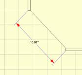 All of the dimensions we have
placed so far have been either horizontal or vertical. It is also possible to
dimension the diagonal distance between two nodes.
This requires that we select Set Aligned Dimensioning from the toolbar or select Aligned from the Right Click Menu.
At this point, dimensioning works the same except that the
dimension line maintains the same angle as the two nodes that were selected and
the distance displayed is not the horizontal or vertical distance between the
nodes but instead it is the diagonal distance between the nodes.
 The page size is automatically set
to the active page size of the current default printer on your computer. If you
want a different page size, set the desired page size in the File Ė Print area. Select the printer or
plotter you want to use and select the proper page size before accessing the Line Drawing Editor.

 The next area to define is called Drafting Parameters. It is accessed
either through the icon at the top or by right clicking and selecting Drafting Parameters.
 Overrun
is how far the extension line extends past the dimension line. All measurements
here are based on the printed page. If you set Overrun to ľĒ, the line will extend past the dimension line ľĒ as
measured on the final printed page.


 Select Rotate Dialog and a dialog screen appears that you can use to
rotate the highlighted cabinet.


 Now, click on a node and move the
cursor away. A dimension line attached to the node follows the cursor.
  Highlight and click on a second
node and a dynamic dimension line appears. Now, the dimension text follows the
cursor. You move this into position and click again to anchor it.
 Actually, every aspect of the
dimension and text position, other than the nodes that define it, can be
repositioned after it has been placed. There are two things you might want to
change on a dimension, the position of the text or the position of the
dimension line itself.
 At times there are a lot of nodes
concentrated in an area making it is difficult to select the exact node you
want. When this occurs, you can easily zoom in and out during the dimensioning
process.
 From this full view of the drawing
page, we will place a dimension line showing the width of the top drawer in the
drawer stack from the front view.


 All of the dimensions we have
placed so far have been either horizontal or vertical. It is also possible to
dimension the diagonal distance between two nodes.