Using the Part Editor
The Part Editor is
used to modify any part of a cabinet or a Display
Panel, Display Board or Display Cube. Not only can you modify
these parts, but for parts made from sheet stock or for profiled edges, the
modification is automatically added to the nest diagram and the required CNC
program to machine the modified part is generated through the CNC feature. The
part is modified by cutting through, pocketing or profiling it.
Modifying a part is typically a two step process. First, geometry
is created on the surface of the part and then that geometry is used to cut,
pocket or guide a profile tool. It is also possible to use the edge of a part
to guide a profile tool but geometry must exist for a through cut or pocket
cut.
There are two different ways to create geometry. Simple
geometric shapes such as a rectangle, circle and filled arc can be defined and
placed on the surface in the Main
workspace. Several geometric shapes can be placed on the surface at once and
the shapes can overlap. These shapes can then be highlighted and used to cut
through, pocket or make a part from.
These simple geometric shapes can be modified, even after
they have been cut by using the Constraint
Manager. For example, to create a pattern of four holes, you could
carefully create correct geometry and then use it to cut the hole pattern. You
could also draw and cut four random circles, which can be done rather quickly,
and then set their position and diameter in the Constraint Manager. See the section “Constraint Management for
Parts Modified in the Part Editor” for more information.
External corners and, once cut, inside corners can be
modified by filleting or chamfering.
More complex shapes are created in a separate area called Contour. This area is more CAD like and
allows the development of more complex shapes and paths. The Contour area either creates open paths
to guide a profile tool or it creates a closed shape that can be used to cut
through or pocket.
The Contour area
can also import two dimensional DXF files to help define the contour. This
allows you to use most popular CAD systems to create geometry for parts or
cut-outs and then bring those shapes into the software.
Before we demonstrate actual pieces, let’s take an overview
look at the Part Editor.
This area is actually quite simple to use but very powerful.
It is essentially a simple CAD system that operates on parts imported from the Cabinet/Assembly Editor.
Start by highlighting a part in the Cabinet/Assembly Editor and pressing the Part Editor icon. The part can be a single part of a cabinet or
assembly or can be a Display Panel, Display Board or Display Cube. This opens the Part
Editor with the part in the work area. The part is oriented flat and can be
worked on from either side.
A part is selected in the Cabinet/Assembly Editor by SINGLE clicking on it. It then displays
with a cross hatched highlight.
In the Part Editor,
text depicting the orientation of the part helps provide orientation. The view
can be changed from front to back or side to side by changing the C-Plane located in a control box on the
taskbar just above the center of the workspace. There is also an X, Y position
readout of the cursor position located next to the C-Plane control.
Although we refer to the Part
Editor as a CAD system, it functions a bit differently than a typical CAD
system.
In most CAD systems you draw lines and surfaces to define
the exterior of a part. Then, if you want to actually make the part, you must
define tools and tool paths that will cut the part from a blank. Finally, the
size of the required blank is determined.
In the Part Editor,
we start with a blank or a basic part and then use defined tools to cut away
material to produce the desired final shape. In doing this we are automatically
defining the required tools and the cutting processes needed to make the part.
This approach makes it possible to quickly and easily machine any part
developed in the Part Editor.
The Part Editor
basically modifies the part in two ways. The first method uses geometry placed
on the surface of the part. The geometry is created by either using one of the
geometry tools such as the Rectangle,
Circle or Filled Arc or by creating a closed geometric shape using the Contour Mode. This geometry is then
selected and the part cut.
The part can be cut in two ways;
-
It can be cut all the way through the part, creating a
hole or cut-out the same shape as the geometry. It can also be cut only part of
the way through the part, creating a pocket the same shape as the geometry.
-
The geometry can be the actual part, cutting away all
material outside the closed shape.
The second basic function of the Part Editor is to cut a profile on the edge of the part or along a
contour on the part.
To cut a profile, a Tool
is required that has the profile you want. This Tool is created in the Shape
Manager and saved as a .tol file.
To demonstrate these features, let’s start with a simple
cabinet box and modify it to have a curved front, profile top and speaker hole.
Open the Cabinet/Assembly
Editor and load the Std. Base
Frameless from the Standard Cabinet
directory.
We will start by creating the curved top and front. You
should perform all function on the cabinet that will require changes in size,
joint construction or overlap before modifying parts in the Part Editor. Once parts have been
modified, no changes can be made to the cabinet that would require the size of
the modified part to change. Should this happen, you will lose all
modifications made in the Part Editor
since the system does not know how to handle these changes as part size
changes.
To prepare for the machining, we need to modify the top of
our cabinet.
From the Main page
of the Cabinet/Assembly Editor, right
click on the cabinet top and select Construction
Settings. This opens the Construction
Settings area on the page that defines the Top.
Change Placement
to Top Flush.
Set the Front Inset
to a -4”, Right Inset and Left Inset both to -1”. Press OK.
The top now overhangs the cabinet box. We will return to the
top later, but first we will place a speaker hole in the left side.
Highlight the left end by single clicking on it.
 Notice that the highlight is a grid
pattern on the entire part. This indicates that the individual part is
selected. When a cabinet is selected, only the outline of the parts is
highlighted. This distinction is important when working with cabinets and
individual parts.
Notice that the highlight is a grid
pattern on the entire part. This indicates that the individual part is
selected. When a cabinet is selected, only the outline of the parts is
highlighted. This distinction is important when working with cabinets and
individual parts.
Then, click the Part
Editor icon.
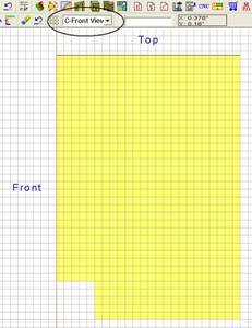
The part is displayed in the workspace as shown.
Notice the position of the “Top” and “Front” of the part is
denoted. From this position information and the knowledge that this is the left
end of the cabinet, we can determine that we are facing the surface of the part
that is inside the cabinet.
We would like to machine from the outside of the cabinet, so
we must change the View.
Change the C-Front
View in the control box circled to C-Back
View.
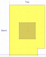
Now you will notice that the “Top” and “Back” are shown and
that we are looking at the outside surface of the part.
We are going to want to cut a ¼ inch deep square pocket into
the side to hold a speaker cover and then cut a circle all the way through the
part.
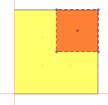
We will start by defining the geometry of the square and
circle.
Select the Rectangle
Tool icon to enter the Rectangle
mode. Note that instructions at the bottom ask you to “Enter the first point
X,Y”. At this point you can either position the cursor over the first point and
click or you can enter the point manually in the box. If you want to use the
cursor, it is almost mandatory that you set the Snap Increment and turn Snap
on. Otherwise it is difficult to achieve a precise position.
 We will use manual input. Type
“6.5,11.5” and press Enter. Positions
are entered in absolute coordinates with the X Axis position entered first,
followed by a comma and the Y Axis position. The origin or 0,0 point is located
at the bottom left corner of the part.
We will use manual input. Type
“6.5,11.5” and press Enter. Positions
are entered in absolute coordinates with the X Axis position entered first,
followed by a comma and the Y Axis position. The origin or 0,0 point is located
at the bottom left corner of the part.
Next, type the end point, “17.5, 22.5” and press Enter. The rectangle is shown in gray.
We will now use this geometry to cut the ¼” deep pocket.
 Click on the Select Mode icon from the toolbar. Then click on the rectangle we
just created to highlight it.
Click on the Select Mode icon from the toolbar. Then click on the rectangle we
just created to highlight it.
From the Right Click
Menu, select Cut Shape. In the
dialog box that appears, put .25” in the Specify
Cutting Depth field and press OK.
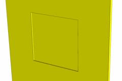
We can now examine the pocket by selecting the Review Mode icon. In this mode, the part
can be rotated and zoomed using the normal controls used for cabinets.
We will now locate a circle over the top of the rectangle.
Select the Circle Mode icon to enter
the Circle Mode.
A circle is defined by specifying the location of the center
and the diameter. Specify the center by typing “12,17” and pressing Enter. Input 10” as the diameter.
Switch to the Select
Mode, highlight the circle and from the Right
Click Menu select Cut Shape. This
time select Cut Through and press OK.
We will next create geometry for the mounting holes in each
corner. From the Circle Mode, create
four circles each .375” in diameter with centers of:
 7.5,12.5
7.5,21.5
16.5,12.5
16.5,21.5
Next, switch to the Select
Mode and click on each to highlight them. Again select Cut Shape from the Right
Click Menu and cut them through.
We could also have placed the large circle and all four
small circles and then cut them all through at the same time. We could have
even placed all the geometry on the part first and then selected entities one
at a time and cut them. This approach, however, can cause confusion because
more than one entity is selected if they overlap at the point you use to
select.
 Placing all the geometry at once
does have the advantage that certain nodes are available for Object Snap, such as the center of a
circle or the corners and center of a rectangle. This can make location of
geometry easier.
Placing all the geometry at once
does have the advantage that certain nodes are available for Object Snap, such as the center of a
circle or the corners and center of a rectangle. This can make location of
geometry easier.
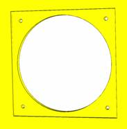
Press Return to
return to the Cabinet/Assembly Editor
and take the changed part with you.
The result on the cabinet is shown to the left.
We modified the left end by using the geometry tools.
Next, we will modify the top using the Contour Mode to create a closed geometric shape that cannot be
developed using the simple geometry tools.
Highlight the top by single clicking on it. Now click on the
Part Editor icon.
The Front is
toward the left and the Left side is
toward the top of the display. This means that we are looking at the top surface
of the top, which is what we want. If this was incorrect, we could use the C-Plane control to change the view.
We want to put an arc across the front of the cabinet. To do
this we need a closed arc geometry with a concave arc. The Arc mode available from the toolbar is a convex arc so we need to
use the Contour mode to create the
geometry.
Press the Contour Mode
icon.
We will use the Snap
functions to create the geometry. Press the Grid
Settings icon and set the Grid
and Snap each to 1” and make sure
they are turned on. The Dotted grid
display is probably the easiest for this application.
Place the cursor at the top left corner of the part. Notice
that the cursor position is 0”,32”. This dimension will be needed shortly.
Select the Circle/Arc
Mode icon, then select Three Point
Arc.
Move 3” to the right to 3”,32” and place the first point.
Now move to the left edge and down to 0”,16”. The 16” is
half the 32” dimension we noted earlier. Place the second point.
Finally, move to 3”,0” and set the last point. You now have
the arc we need.
We must now turn this into a closed geometry so we can use
the Cut/Pocket Using Closed Contour
function.
Switch to the Line
Mode and freehand some lines to close the shape. Their actual position is
not important since only the arc will actually be used to cut the part.
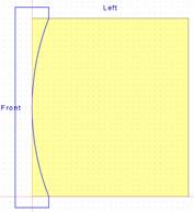 Create lines as shown to develop a
closed geometry that we can use to cut the front arc.
Create lines as shown to develop a
closed geometry that we can use to cut the front arc.
Now, exit the Contour
Mode by selecting the Exit Contour
Mode icon from the toolbar.
We now want to cut this shape through the part. Geometry
created using the geometry tools (circle, rectangle, etc.) use the Cut/Pocket Using Closed Contour function
to cut. Geometry created with the geometry tools use a function called Cut/Pocket Using Geometric Shapes to perform the same function.
 The system will try to help you
determine which function to use based on your operation.; If you have placed
geometry and have highlighted it, it will only offer the Cut/Pocket Using Geometric Shapes and the Cut/Pocket Using Closed Contour will be grayed out. If you have a
defined closed contour and no geometry is highlighted it will offer Cut/Pocket Using Closed Contour and will
gray out the Cut/Pocket Using Geometric
Shapes option.
The system will try to help you
determine which function to use based on your operation.; If you have placed
geometry and have highlighted it, it will only offer the Cut/Pocket Using Geometric Shapes and the Cut/Pocket Using Closed Contour will be grayed out. If you have a
defined closed contour and no geometry is highlighted it will offer Cut/Pocket Using Closed Contour and will
gray out the Cut/Pocket Using Geometric
Shapes option.
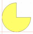
Now back to our part. From the Right Click Menu, select Extrude
Cut. Then, click on any of the lines in the contour. The entire closed
contour highlights.
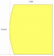
Now press Done to
access the cut dialog. Check Cut Through
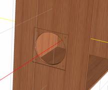
and press OK. The part is cut as
shown to the right.
We now want to put a profile on the front and the left and
right edges of the part.
Select the Profile
Part icon.
Since we are not going to go all the way around the edge but
will cut more than one edge, we need to select Partial at the bottom of the display.
The guide at the bottom tells us to “select the first
entity”. Click on the bottom (cabinet right) edge. Click near the back which is the right hand
side of this edge. The direction around the part that the partial chain will
take is determined by the location that you select. If you select the right
side of the bottom edge as the starting point, the profile will move away from
the corner closest to the point you selected, in this case it will move
counterclockwise around the part. If you select the left side of the edge as
the starting point, the profile would move to the right and counterclockwise
around the part.
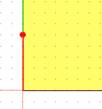
At the bottom left starting point you will see the symbol
shown. The red line with the dot indicates the starting point of the cut and
the direction. The red dot is in the direction of the cut.
Then we need to “Select the last entity” which is the top
(cabinet left) edge.
Now press Next to
indicate you are finished with the path selection.
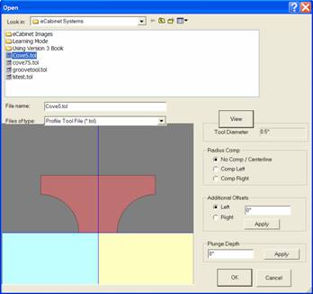
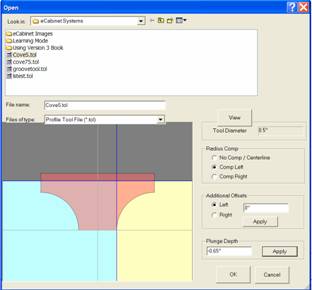
Using the dialog, find the path and file name where you
saved the profile “Cove5.tol” and select it.
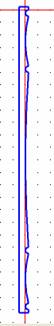
Press View to see
the tool profile.
The blue and yellow areas beneath the tool signify the part.
We must now set parameters that define how the tool cuts the part.
If you select No
Comp/Centerline, the center of the tool will cut along the path.
If you select Comp
Left, the tool shifts to the left and the part is represented by the yellow
area on the right.
If you select Comp
Right, the tool shifts to the right and the part is represented by the blue
area to the left.
Next, input the plunge depth and press Apply.
Note that movement downward and into the part is the
negative direction and movement upward and away from the part is the positive
direction.
The image to the right shows our tool with Left Compensation and plunged -.625”
into the part. Our part is represented by the yellow area.
The left or right designation for cutter compensation is
determined by standing behind the cutter bit and watching it cut away from you.
The direction to the left is left compensation and the direction to the right
is right compensation.
The Additional Offset
area allows you to offset the tool, left or right, in addition to the offset
that occurs from tool radius compensation.
The actual offset caused by tool radius compensation may change
at the machine if the diameter of the tool changes. If the machine operator
indicates that the diameter of the tool has changed, due to sharpening for
example, the system will automatically shift the tool to compensate for the new
diameter. This insures that the final part is the correct size.
 At this point it is simply a matter
of pressing OK.
At this point it is simply a matter
of pressing OK.
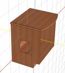
You now see the part with the profile cut along the edges.
Now press Return
and indicate you want to take the changes with you.
The result is the cabinet shown to the right.
The basic techniques shown here will work for sheet
material, either a cabinet component or a Display
Panel.
Using a Display Panel
for a part rather than an actual part of the cabinet has some advantages. When
you use an editor, such as the Shelf/Partition
Editor or the Face Frame Editor,
the entire geometry of the cabinet regenerate as you leave to incorporate the
change you made. This regeneration may resize parts as part of the process.
The system cannot resize a part that has been modified by
the Part Editor so, if the cabinet
regenerates, you lose any modifications you made to any part of the cabinet.
There is a warning about this if you try to enter an Editor with modified
parts.
This can be avoided by waiting until all adjustments that
require editors have been completed and then using the Part Editor to modify parts of the cabinet. A second choice is to
make a Display Panel the same size as
the cabinet part and replace the cabinet part with it. Then you can modify it
without the danger of losing the modifications.
This Display Panel
will not resize, however, you can regenerate the cabinet without affecting the Display Panel. If the changes you make
to the cabinet requires that the part actually change dimensions, you will need
to create a new part of the correct size.
We will next demonstrate some other techniques that can be
used to develop different types of parts.
As an example, we will develop a curved door. This same
approach can be used with a large Display
Cube to create a curved wall for a room.
To do this we will start with a New screen in the Cabinet/Assembly
Editor.
Next, load a Display
Cube 4” Wide, 12” long and 30” Deep. Give it a wood texture you like.
Then click on it to highlight it and press the Part Editor icon.
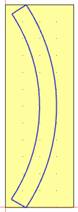 We will use the Contour Mode to create a closed shape we
can use to make the cut.
We will use the Contour Mode to create a closed shape we
can use to make the cut.
Press the Contour Mode
icon to enter the Contour Mode.
Use the Three Point
Arc and Line tools to develop a
shape as shown to the left. Make sure you used the Fillet (with zero diameter) or Trim
tools to be sure you have a closed contour.
Exit the Contour Mode.
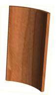
Right click and select Create
Part Using Closed Contour.
The result is shown at the right.
 Press Return and keep the changes.
Here is our door. It has the correct shape but doesn’t look
very good. The grain texture is warped and does not look realistic. This is the
result of how grain is mapped to parts in the Cabinet/Assembly Editor.
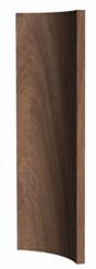
We will fix this by converting our part into a Display Object using the Display Part Editor.
We will Export the
part as an HSF, then load it into the Display
Part Editor, adjust the grain and appearance and save it. We can then load
it back into the Cabinet/Assembly Editor
as a Display Object.
 Highlight the door by clicking on
it.
Highlight the door by clicking on
it.
Then from the File
menu at the top left, select Export
Selection. This will export whatever is highlighted as an HSF file. Give it
a name and directory.
We can now go to the Display
Part Editor, load the file and adjust the grain appearance and then save it
again. Now its appearance is quite acceptable.
 This technique adds a powerful
capability to the system. For example, if you wanted glass shelves in a
cabinet, you could highlights the shelves, Export
them, change them to glass appearance in the Display Part Editor. Then you could load the resulting Display Object back into the Cabinet/Assembly Editor and locate the
new glass shelves.
This technique adds a powerful
capability to the system. For example, if you wanted glass shelves in a
cabinet, you could highlights the shelves, Export
them, change them to glass appearance in the Display Part Editor. Then you could load the resulting Display Object back into the Cabinet/Assembly Editor and locate the
new glass shelves.
We will now develop a corner post for a cabinet with a V
notched out where it meets the cabinet.
Return to the Cabinet/Assembly
Editor and press the icon for New
and say Yes you do want a new page.
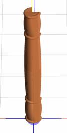
We started in the Shape
Manager where we created the shape of the leg we want as shown to the left.
This was then made into a tool and saved. See the chapter on the Shape Manager for details on how this is
done.
Next, in the Cabinet/Assembly
Editor, create a Display Cube 3”
W x 3” H x 24” D.
Highlight the part and press the Part Editor icon.
 Once in the Part Editor, we will cut the corner notch first.
Use the Rectangle
tool to pace a rectangle that extends from the center of our block to the edge
as shown. Highlight the rectangle, right click and select Cut/Pocket Using Geometric Shapes. Select Cut Through and press OK.
 Now, press the Fillet icon and set the Fillet
Radius to 1.5”. Be sure to press Enter
to make the dimension active.
Now, press the Fillet icon and set the Fillet
Radius to 1.5”. Be sure to press Enter
to make the dimension active.
Apply the fillet to the remaining three corners. The result
is a round post with a corner notch as shown.
Next, we will apply the tool we developed for the leg to the
outside of our part.
Press the Define Cut
Path icon. Select Partial to
indicate that we will not be cutting along a path that is closed.
Next, click on the lower right quadrant of our post to
indicate that this is the starting segment of our partial chain. Then click on
the upper left quadrant when asked for the end segment.
Press Next to move
to the next step.
Select the tool you saved and press OK.
The shape of the tool is cut into the post.
Press Return and
take the changes back to the Cabinet/Assembly
Editor.
We can see the result to the left. It has the proper shape
but again, we need to convert it to a Display
Object to get a really good appearance.
Reset to the front view and highlight the part. From the File menu selection at the upper left,
select Export Selection. Save the
post as an HSF file.
Open the Display Part
Editor and adjust the grain image. The most common adjustments are the Texture Scale and Rotate.
Then save the part as an HSF. This can now be loaded into
the Cabinet/Assembly Editor or into
the Custom Layout. Note that you can
also Export from the Custom Layout.
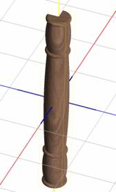 The finished post shown to the
right has been given a walnut grain which has been sized and rotated until the
appearance shown was achieved.
The finished post shown to the
right has been given a walnut grain which has been sized and rotated until the
appearance shown was achieved.
As you can see from these exercises, the Part Editor is a powerful tool and
allows you to produce almost anything.
The thing you don’t see is that most of what you design can
be machined using a Thermwood CNC router.
A really powerful feature is the ability to model a profile
edge and then machine it without requiring a matching profile cutting tool.
The CNC router is able to do this by developing a modeling
program from the data sent to it by the eCabinet Systems software. This is all
done inside the Thermwood CNC control.
The modeling program starts with a ball nose cutter. It
traces the path of the profile. Then it shifts over slightly and traces the
path again. It goes back and forth along the path, shifting over a little each
pass until the basic profile is generated. Then, if there are sharp inside
corners that the ball nose tool couldn’t reach, it uses a flat bottom tool to
trace those. It can also use a pointed liner tool to cut sharp lines if
required by the design.
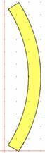
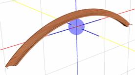 This process is automatic and can
be used to generate profiles on straight or curved parts. It can cut moldings
like the one shown here. It can cut profiles on the edge of parts such as table
tops or raised panels for doors.
This process is automatic and can
be used to generate profiles on straight or curved parts. It can cut moldings
like the one shown here. It can cut profiles on the edge of parts such as table
tops or raised panels for doors.
The ability to model profiles is part of the initial release
of Version 4 and the software you are using right now generates the CNC files
needed to do this. Additional capability is planned for future releases.
For example, in this guide we used a highly impractical 24”
tall tool to generate turnings and posts. In future versions of the software, a
turning capability is planned using the Shape
Manager and Part Editor. This
will make developing turnings easier but, the primary purpose is to
automatically generate files needed to actually machine the turning on a
Thermwood CNC router equipped with a rotary playback axis. The rotary playback
axis is currently available as a machine option.
The current system can model virtually any molding or edge
profile shape. In the near future you will also be able to create and then
machine turnings quickly and easily.