The primary purpose of the Shape Manager is to create shapes or profiles. These shapes or profiles can then be used to create profile tools which can then be used to cut a profile on a cabinet component in the Part Editor. In future releases, the Shape Manager will be expanded to develop and save shapes, such as the shape of a cut-out for a sink, which can then be imported into the Part Editor and added to a part.
Tools created by the Shape Manager are a bit different than what you are used to. You can, of course, create symmetrical tools that will then function like a router bit. In addition, you can create non-symmetrical tools, that is tools that are different on one side than the other or even tools that only have one side.
The tool shape you create in the Shape Manager is swept along a path defined in the Part Editor. The tool does not rotate, it just moves along the path sweeping out the shape, almost magically. Obviously since the tool is not symmetrical, it will create a different result if it is swept along a path in one direction rather then the other. This means that when using non-symmetrical tool, you must pay special attention to the direction you are cutting.
A good way to visualize the way a tool will cut is to imagine you are standing behind the tool shape and it is cutting while moving away from you. This is also a good way to visualize Right and Left directions for tool compensation and other adjustments. We will cover those shortly.
You might wonder whether you could ever cut a profile made by a non-symmetrical tool, especially a groove where the profile on one side of the groove is different than the groove on the other side. Surprisingly, the answer is yes.
The cut is not machined by a traditional tool but instead is “modeled”. This uses a small diameter ball nose cutter and a small diameter square bottom tool. The ball nose tool moves along the profile, shifting over a small distance each pass until the basic shape of the profile has been generated. Then, sharp inside corners are finished using the square bottom tool. This same approach works on a symmetrical cut when the required profile cutter is not available. It can be especially valuable on wide or complex moldings where tooling cost might otherwise be substantial.
Profile tools are created by first creating a closed geometric shape and then using this shape to create the tool. Geometric shapes created in this area can be saved and then loaded and used again.
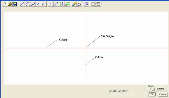
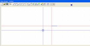
The Shape Manager operates in a separate window and consists of a basic two-dimensional CAD system. The background grid appearance, axes display and pick box size are controlled through Grid Settings reached through the Grid Settings icon or through the Grid Settings selection from the Right Click Menu.
While working in the Shape Manager, an area to the lower left offers step by step guidance for each function. There is also a place to enter X,Y positions manually.
The point where the X and Y axes cross is the Origin or the 0,0 point. The vertical Y Axis represents the centerline of the tool. The Origin or 0,0 point should be located at the bottom of the shape that defines the tool.
The Zoom Controls allow you to zoom in and out using either the + and – buttons on the display or using the + and – keys on the keyboard. In addition, you can hold the Ctrl key and pull a blue rectangle over the area you want to zoom to.
The Entities button zooms the scene to just include all the entities that currently exist.
The scene can be panned left and right and up and down using the arrow keys. If it doesn’t seem to move, open the Right Click Menu and check that the Pan Move Increment is not set to zero.
A background grid and axes displays can help keep you oriented during the drawing process. These are controlled through a dialog accessed by pressing the Grid icon.
Also, because you are generally working in a smaller scene when creating tools, a Local Settings/Preferences dimension display is available through the Local Settings/Preferences icon. This allows you to select a numeric display for this area that is different than the rest of the program. Changing the numeric display here will not affect the display anyplace else except here.
Geometry is created using a series of tools, accessed by right clicking. Some of these tools (line, arc, circle, spline and mirror) create geometry. Others (fillet, chamfer, extend, trim, move and offset) modify geometry. Together, they can draw any two dimensional geometric shape. The same CAD engine used here is also used in other areas of the program. Once you learn how it functions, you will be able to use it in each of these areas.
Each of the tools that create geometry requires that points be precisely located. There are two ways to accurately locate points. First, you can type the X and Y coordinate position of the point by typing the X position, then a comma, then the Y position. Be sure to use a – sign for X positions to the left of zero or for Y positions below the zero point although normally the zero position on the Y Axis is the bottom of the tool.
The second way of precisely locating points is to set the grid spacing to an increment from which all required points can be reached and then turn on Snap. The cursor will then position on the grid points and it is simply necessary to move it to the desired point. It is normally necessary to zoom in enough that the individual grid points are far enough apart that they can be accessed easily.
Object Snap is another useful tool. With Object Snap turned on, the cursor will snap to the end point of a line or arc if it is within the Pick Box when the mouse is clicked. This assures that there is a continuous unbroken path between geometric entities which is important when you begin to use the geometry to create a tool.
The tools used to create geometry are straightforward and the Guide Info area displays each step as you do it.
Create lines by specifying each end point.
Create a three point arc by specifying the start point, one intermediate point and the end point.
Create a circle by specifying the center and the radius.
You can also create a Spline curve, which is a smooth curve through several points. Enter the Spline mode and begin specifying points on the curve. Press Esc to exit the Spline mode.
Once created, these entities can be mirrored or modified.
To create a mirror image of geometry, start by highlighting the geometry you want to mirror. Then press the Mirror icon and indicate what you want to mirror the geometry about. You can mirror about the X Axis, the Y Axis or a line.
A Chamfer or a Fillet can be placed at the intersection of two lines or arcs. To modify a Chamfer or Fillet you must first erase the existing Chamfer or Fillet using the Delete mode and then define the new one.
Lines, arcs and circles can be trimmed at their intersection.
To trim a single line at an intersection, select Trim-Trim One, click on the line portion you want to keep, then click on the entity that it intersects with.
If the original line extended past the intersection, it will be trimmed to the intersection point and the section of the line you didn’t click on is discarded.
If the original line did not extend to the intersection, it is extended until it intersects.
To trim two lines at their intersection, select Trim-Trim Two, click on the portion of the first line you want to keep, then click on the portion of the second line you want to keep.
If the two lines intersected, they are trimmed at the intersection point, keeping the portion of each you clicked on.
If either line did not extend to the intersection, it is extended until it intersects.
Note, in either case, arcs extend along the arc path to the intersection.
When trying to create a tool from your geometry, at times, you may be notified that the path you selected is not a closed path. The Trim Two function can be very useful in correcting this. Simply trim each intersection until the open intersection has been closed.
A Circle can also be trimmed. To understand how this works, think of a circle as a 360 degree arc with both the start and end points located at 3 o’clock to the right.
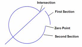 The circle is then made up of two
sections, one that starts at 3 o’clock
and extends counterclockwise to the first intersection and a second section
that starts at the intersection point and extends counterclockwise back to the 3 o’clock or zero position.
The circle is then made up of two
sections, one that starts at 3 o’clock
and extends counterclockwise to the first intersection and a second section
that starts at the intersection point and extends counterclockwise back to the 3 o’clock or zero position.
When trimming, the section of the circle you first click on will remain and the other section is discarded.
In the above example, if you click on the section labeled First Section and then select the line, the entire arc labeled Second Section is trimmed leaving only the first section.
If you click on the arc labeled Second Section and then click on the line, the arc labeled First Section is trimmed away leaving the arc labeled Second Section.
Sometimes when trimming a circle, you may need to perform the trim operation more than once. For example, if you wanted to keep the arc located above the line, you first need to trim away the first section. Now it is no longer a circle but is an arc and will trim like an arc segment. Perform a second trim to remove the arc between the zero point and the line by clicking on the arc above the line and the trimming to the line.
To keep the arc below the line, click on the second section below the line and trim to the line. In this case, everything from the intersection to the lower left to the zero point will be gone. Then, trim the lower arc back to the line and it is extended until it meets the trim line.
Experimenting with trimming circles combined with the above explanation will make this clear.
Lines and arcs can be extended by a fixed distance by selecting the Extend icon. A dialog will ask for a distance to extend. After entering a distance, whichever end of a line or arc you click on is extended. Note that arcs extend along the curved arc path.
 The Offset command, when applied to an entity, either creates an offset
copy of the entity or offsets the entity a fixed distance. This command is
executed by selecting the Offset icon
or selecting Modify – Offset from the
Right Click Menu. In the dialog that
appears, you set the offset distance and select whether the entity is copied or
moved. Then, click on the entity you want to offset and then click the side of
the entity you want to offset to.
The Offset command, when applied to an entity, either creates an offset
copy of the entity or offsets the entity a fixed distance. This command is
executed by selecting the Offset icon
or selecting Modify – Offset from the
Right Click Menu. In the dialog that
appears, you set the offset distance and select whether the entity is copied or
moved. Then, click on the entity you want to offset and then click the side of
the entity you want to offset to.
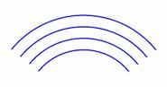
Offset straight lines are the same length as the original. Offset arcs have the same included angle as the original as seen to the right.
The Move command is used to move and existing entity. The entity must be selected BEFORE the Move command is initiated. Press Esc to cancel any current modes and enter the select mode and click on the entity you want to move. Then press the Move icon or select Modify-Move from the Right Click Menu. You will now define two points. The entity will move a distance the same as the relative distance between the two points.
Entities can be deleted by entering the Delete mode. Press the Delete icon or select Delete from the Right Click Menu and several Delete modes are available.
Single Delete will delete any single entity that you click on. When in this mode, any single entity you click on is deleted.
Inside Window will open a mode where you can pull a red rectangle or window using the mouse. Any entity that is completely within the window is deleted. An entity that touches or crosses the window frame is not deleted, the entity must be completely inside the window.
Inside Intersect Window also opens a mode where you can pull a window, however, in this mode any entity that has any part of it inside or touching the window is deleted.
Finally, All Entities does just what it says, it deletes everything.
Undo can be a lifesaver. It reverses or undoes that last thing you did. It only goes back one step, however, pressing it reverts to the state you were in prior to the last action you took.
Once the geometry is complete, you can create a tool using the Create Tool icon or by selecting Create Tool from the Right Click Menu. To create a tool, you must have closed geometry. This means that the outline must be a continuous closed curve with no gaps or openings.
 Tool shapes should generally be
drawn symmetrical with their full shape. It is possible to draw a tool whose
left and right sides have different profiles and, when applied to a part, it
will cut a different profile on each side of the cut. You cannot use a rotating
router bit to actually cut this shape, however, as discussed earlier this asymmetrical
shape can be modeled using standard modeling tools.
Tool shapes should generally be
drawn symmetrical with their full shape. It is possible to draw a tool whose
left and right sides have different profiles and, when applied to a part, it
will cut a different profile on each side of the cut. You cannot use a rotating
router bit to actually cut this shape, however, as discussed earlier this asymmetrical
shape can be modeled using standard modeling tools.
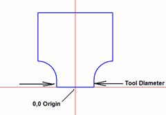
The tool diameter is the shank diameter from the beginning of the cut profile on one side to the cut profile on the other side. This is also generally the diameter of the shank that mounts in the router collet. This diameter will be needed when the tool is applied to an edge in the Part Editor.
To create a tool file you simply need to press the Create Tool icon, then select the closed curve by clicking on it to highlight it. Press the Next button then specify a file name to save the tool under.
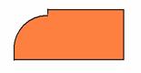
We will now develop a simple tool as an example. The image to the right shows the edge part profile we would like to create a tool for.
Open the Shape Manager and select Line Mode. We will use numeric input for this design.
We will make the tool ½” shank diameter.
Start at 0, 0.
The second point is .25, 0. .25 is in the plus direction on the X axis, which is to the right. We now have our first line which defines the bottom of the bit.
It is now a good idea to zoom to the area we will be working in.
Hold the Ctrl key and pull a blue rectangle over the working area.
Here is what we have so far, after zooming.
Notice that we are still in the Line mode. When a mode is selected, you remain in that mode until you either change it or press Esc, which puts you is a default or Select mode. This allows you to select individual entities, primarily so that you can Move them.
 We will now create the circle
segment on the right side of this line. Make sure Object Snap is turned on by right clicking the mouse and verifying
that it is checked.
We will now create the circle
segment on the right side of this line. Make sure Object Snap is turned on by right clicking the mouse and verifying
that it is checked.
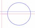
The circle will have a ½” radius so enter the Circle – Circle mode. Input .75,0 for the center of the circle. Then, place the pick box over the right end of the line and click. A circle is created.
We need to trim the circle, but first we will add the rest of the straight line which we can then use in this trimming process.
Enter the Line Mode.
Draw the first line from .75, 0 to .75, .75.
 Finally, click on the top of the
line we just drew and input the end of the line at 0, .75 creating a line across
the top to the Y axis.
Finally, click on the top of the
line we just drew and input the end of the line at 0, .75 creating a line across
the top to the Y axis.
This is the result so far.
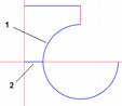
We are now ready to trim the circle. This area can get a little tricky so we will detail it step by step.
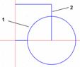
Select the Trim Mode – Trim Two.
Select the upper left quadrant of the circle marked (1) as the first entity to trim. Then select the upper portion of the line marked (2) as the second entity to trim.
 The image to the right shows that
the circle from the zero point to the right to the line we selected has been
trimmed. The line has also been trimmed, keeping the segment we clicked on.
The image to the right shows that
the circle from the zero point to the right to the line we selected has been
trimmed. The line has also been trimmed, keeping the segment we clicked on.
Now we need to trim the bottom two quadrants of the circle.
 In the Trim Two mode, click on the upper left quadrant of the circle
indicated by (1), indicating that this is the segment we want to keep. Then
click on the line (2).
In the Trim Two mode, click on the upper left quadrant of the circle
indicated by (1), indicating that this is the segment we want to keep. Then
click on the line (2).
The result is shown to the right.
We have now created the right side of our tool. We will use the mirror command to create the left side which is an exact mirror copy of the right side.
 Click on the Select arrow from the
toolbar and then select All. This
highlights the geometry we have already created.
Click on the Select arrow from the
toolbar and then select All. This
highlights the geometry we have already created.
Click on the Mirror icon and check that we want to mirror the highlighted geometry about the Y axis. Press OK and we have the completed tool geometry as shown.
We can save this geometry if we need to use it again in developing another shape. In this case, we will simply make a tool using this shape.
Press the Create Tool icon, select the geometry we just created and press Done.
A dialog now asks for the diameter of the tool. The diameter requested is the diameter referred to earlier, from the beginning of the cutting surfaces of the tool. For this tool it is .5”.
You can now specify a directory and file name to save the tool under. We will call it “cove5.tol”. Note, the “.tol “ extension indicates a tool file in eCabinet Systems.
Although this is a relatively simple example, it does illustrate several techniques for using the geometry tools in the Shape Manager. As you work with the program, you will develop methods and techniques of your own.
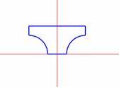
We will now address one additional feature that might be useful, a non-symmetrical tool.
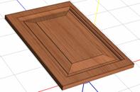
 Here we have created a
non-symmetrical tool that we can use to make a simulated raised panel door.
Here we have created a
non-symmetrical tool that we can use to make a simulated raised panel door.
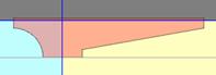
Obviously, this tool cannot actually be made as a rotating router bit. It can however, be used in eCabinet Systems to create a machined channel in a part that has a different profile on each side as shown.
 Depending on the actual shape, the
resulting part may not be able to be machined using traditional techniques.
Depending on the actual shape, the
resulting part may not be able to be machined using traditional techniques.
When sent to a Thermwood CNC router, however, these shapes can be modeled.
Modeling consists of machining with a 1/8 or 1/4 inch ball nose router bit that steps over .01” to .02” each pass as it develops the shape. Square inside corners are then machined using a square bottom bit.
The Thermwood control automatically develops the modeling program needed to make a part if a tool does not exist with the correct profile. Since a non-symmetrical tool doesn’t really exist, any non-symmetrical machining must be modeled.
This ability to model almost any profile without specially ground tooling can dramatically decrease costs when a limited amount of production is needed. It also dramatically increases flexibility for shops that build custom products.
If the channel in the part is cut with a rotating router bit, inside corners are typically round with the same radius as the router bit. If you create a contour with square corners, the inside profile will be squared off as shown.
In this version of the software it is not possible to create a profiled corner on an inside cut that has a radius less than the radius of the router bit at its largest radius. For example, on our tool, the minimum fillet you can use is .75” which is the largest radius of the tool. At least for now, if you want to simulate the effect of the radius corner that results from using a router bit, you will need to use a fillet equal to the radius of the tool. This area will be addressed in future releases of the software.