
A Display Cube is essentially a cube, of any size on which we can place a texture image. It is one of the most powerful tools you have for creating realistic custom layouts. It can be used for pillars, beams, hearths, rugs, appliances, fireplaces, cereal boxes, books and a thousand other common items that will make your presentation better. They can even be created in the Cabinet/Assembly Editor taken to the Part Editor and machined into almost anything.

The best way to learn the use of Display Cubes is to run through some examples. Earlier, we use display cubes to simulate a fireplace hearth. Let us see exactly how we did this.
From Detail Room, select Display Cube from the list under Select Item to Install.
The dialog to the left appears.
In this case, our digital images were of a six foot section of the hearth so we will create two display cubes.
We took the original image of the left side of the original hearth and flipped it horizontally to create a second image we will use on the right cube.
Although this image appears compressed, the original image was long and narrow. The software compressed it for display here but will use the original image for the cube.
In this case, we will set the cube width to 6 and the length to 2.
The reason that we do this is that the width is the left to right dimension and the length is the up and down direction.
Our image is compressed but the original long dimension is left to right so we make that the 6 dimension.
Check Stretched to indicate how the image is to map to the cube and then press OK.
The cube appears in the room, at floor level and highlighted.
The first thing we want to do is rotate it 90 degrees.
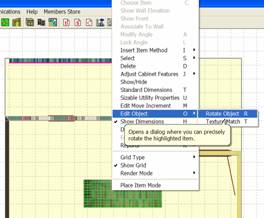
Right click, then select Edit Object and Rotate Object.
This brings up the rotate dialog.
We want to rotate about the Z axis 90 degrees.
If you click on the slider, it will move in 90 degree increments.
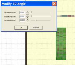 The hearth is now properly rotated
and since it is already on the floor, it is ready to move into position.
If the height above the floor was not correct, it can be moved up and down using the U and D keys, U for up and D for down.
It moves the Edit Move Increment each time a key is pressed.

We can now move it into position to the lower left of the wall by holding the Shift key and using the right mouse button.
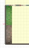
It can also be moved by holding the Shift key and using the arrow keys.
Here the first half of the hearth is in position.
Double click on it to deselect it.
 Repeat the process for the second
half of the hearth, making certain to select the second, right hand image.
Here you see both halves of the hearth in position.
Double click on the second half to remove the highlight and press Done.
The result is a realistic hearth made of two brick image covered Display Cubes.
When a Display Cube is created, the image selected is placed on all six sides.
It is stretched and skewed as needed so that one copy of the image is placed on each surface.
Sometimes you need a cube that has a different image on one surface or another.
For example, you may need a special range, which is a three dimensional object that has a different image on the top and front.
In these cases, you may need to combine two or more Display Cubes to get the effect you want.
To demonstrate, we will develop a gas range using images obtained from the web.
Here you see an image of the range we would like to simulate.
It is shown loaded into IrfanView, which is the image control software that starts when you press the Image Control icon on the toolbar. Everything we do to images in this manual is done within eCabinet Systems using this software.
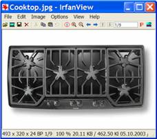
If you look closely, you will see that we have pulled a highlight rectangle over the very front of the range.
We will crop the image to this area and save it under a new file name.
Then we will do the same thing to the backsplash.
For the top, we could not find the exact range top but we found one that is similar and will use it.
Since it is black, details will not be all that visible.
The overall accuracy of presentation is dependent on each user and you need to make decisions about what is and is not acceptable yourself.
Now we will create the first cube, which is the range body itself.
One area that can be confusing is determining how to map the image to the actual cube for use in the room.
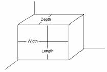
The diagram to the right shows the cube as it sits in the room.
The front surface is the Width and length.
The Depth is the distance front to back, just like the cabinets.
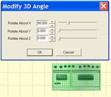
When the cube is first displayed, it will be turned 90 degrees on the X Axis with the front face facing upward.
You need to turn it 90 degrees as shown before you can use it.
This is the easiest way to get the effect we are looking for.
 If we try to create the cube
already in the correct orientation, the image will be upside down requiring
even more manipulation.
Now we move it to the wall as shown using the Shift key and left mouse button.
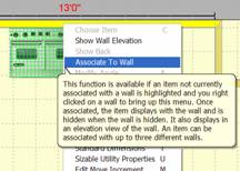
We then right click on the wall and select Associate to Wall.
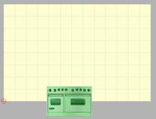 We are going to adjust the height
of the range from the elevation view of this wall.
For the range to display in the elevation view of the wall it must be associated to the wall.
Next, right click on the wall again and select Show Wall Elevation.
The range is actually located partially under the floor.
This is because it was first generated on the floor and when we rotated it, the height of the range was greater than the depth so part of it rotated under the floor. This will occur many time when working with Display Cubes so be prepared for it.
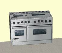 You can move it up by holding the Shift key and using the left mouse
button. (Make sure you are in the Free
Style mode). You can also use Shift
and the up arrow key.
Here we see the range and the front looks pretty good but the top clearly needs help.
Using the same technique, we will create a top using the range top image.
It will only be an inch deep.
We will also create another cube for the backsplash and use the backsplash image we took from the original range image.
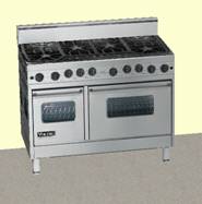 Here is the completed range made
from display cubes.
We added additional cubes 2x2x5 with the backsplash image to create the feet.
The result is very pleasing and adds to a customer presentation.
This particular appliance was developed in the Custom Layout area. You could also create it in the Cabinet/Assembly Editor and save it as an assembly. This might actually be easier since positioning Display Cubes in space is easier in the Cabinet/Assembly Editor than in Custom Layout.
Display Cubes can be used to simulate a wide variety of items in a room. They can be used for beams, pillars, doors, ceilings, etc.
As noted earlier, cabinets will not obey the clearance settings for appliances specified in Standard Dimensions when appliances are created in this manner.
If you want to use this feature, you can size and place the system appliances and then after the cabinet have been located, delete the system appliances and replace them with these Display Cube appliances.