There are a lot of different internal components used in cabinets including nailers, stretchers, webs, supports and sleepers among others. For purposes of this discussion we will call all of these “stretchers” regardless of their ultimate purpose.
Within the software stretchers are made from sheet stock and are nested along with other components made from the same material. You can make these from a board stock material by creating a new “sheet” material that is actually a board and specifying the size as 12” x 96” for example. Then when you actually produce the job you must remember that this particular material is a board stock even though the software treats it like sheet stock.
Stretchers can be positioned in a base or upper cabinet horizontally from side to side, vertically from top to deck or horizontally from front to back. A stretcher can also connect to any other fixed cabinet part such as fixed shelves, partitions or other stretchers.
For corner cabinets, stretchers are limited to nailers located against the cabinet back or sleepers located under the deck.
Stretchers can be given any joint construction with parts it contacts.
Stretchers are added to a cabinet in an area called Stretcher Editor accessed from the top toolbar.
Left-Right, Up-down and Front-Back stretchers can be placed in base and upper cabinets. Nailers and sleepers placed on corner cabinets are covered in a separate section of this manual.
For non-corner cabinets we start by defining the two cabinet parts that the stretcher spans between. Then we move, adjust and define how the stretcher acts as the cabinet size changes.
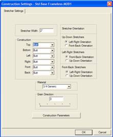
The way stretchers are initially added is defined by the Add Stretcher Settings area in Construction Settings. Let’s start by examining these settings.
The first parameter is the Width. When combined with the Material which defines the thickness, we have the physical dimensions of the stretcher. As you will see, this width dimension is not all that important because the parametric nature of the Stretcher Editor makes it quite easy to adjust this after it has been placed. If you know the exact width, no reason not to put it here and save some time later.
In the Construction area you specify the type of joint between the stretcher and other components. This is an important feature.
As long as the stretcher is perpendicular to and not positioned at an angle with another component and is against that component, it can be directed to make any available joint with that component. Therefore, a stretcher can have any joint with any cabinet component it contacts. It can also have a defined joint with any other stretcher it contacts. This is a powerful feature although it can be confusing until you get used to it.
The joints specified in Construction Settings refer to directions as seen from the cabinet itself. Therefore, if you set Top to Blind Dado, a horizontal stretcher whose top edge contacts the cabinet top is given a blind dado along that edge. Another stretcher that is positioned vertically from the top to the deck will find the top end has a blind dado joint.
This is an area you need to play with awhile to become comfortable.
The third area defines initial orientation of the stretcher. Each time a stretcher is placed between two components, it can have either of two orientations. For example, a stretcher placed between the left and right ends of the cabinet can be oriented Front-Back like a shelf or it can be oriented Up-Down like the cabinet back.
For purposes of these definitions, we define three types of stretchers, Left-Right Stretchers, Up-Down Stretchers and Front-Back Stretchers. Each can then be initially oriented in either of two directions. You can later rotate them to any angle if you want but initially they are one way or the other.
Grain Direction works like other components and Construction Parameters define geometric characteristics of the various joints.
Now let’s focus on the Stretcher Editor and see how a stretcher is added and adjusted. We will use an example to show how this area functions. Let’s add a stretcher from the left to the right side of a cabinet.
In the cabinet/Assembly Editor we have loaded the Std. Base Frameless. Click on the Stretcher Editor icon to open the Stretcher Editor. You have all the standard grid settings and display options available by right clicking and selecting Grid Settings. We will now designate the two parts that we want the stretcher between, in this case the left and right ends.
We will highlight the left end first, then the right end by clicking on each. The first part you highlight is the “control” part and will be used to adjust and refine the stretcher. Now press Add Stretcher.
You are now presented with the Add Stretcher Settings from Construction Settings which you are free to modify as needed. Press OK and you now have a stretcher in the center of the end panel. This is likely not exactly where you want it so we will adjust the stretcher.
 Click on the stretcher to highlight
it and press Adjust Stretcher. You
are presented with the screen shown. Let’s look at this information carefully because
understanding it is key to positioning and defining stretchers.
Click on the stretcher to highlight
it and press Adjust Stretcher. You
are presented with the screen shown. Let’s look at this information carefully because
understanding it is key to positioning and defining stretchers.
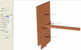
The display in the center can be rotated, moved and zoomed like most other images. Sometimes you need to rotate and move the image to see certain Insets. Also, if the part becomes too complex, you can turn off the display of certain Insets by unchecking the Show box across from it.
The area to the left controls the display, insets and locks and understanding the relationships between these is vital to understanding how to adjust stretchers. This can get somewhat involved at first but is fairly simple once you understand it.
 Let’s start by leaving the Locks off and adjusting the Insets. Basically the Insets define the distance from the
stretcher to the boundaries of the part. Insets
1,2,3 and 4 are the distances
from the stretcher to the edges of the left end as shown. Inset 5 is the distance from the end of the stretcher to the
surface of the left cabinet end, in this case zero. Inset 6 is the distance from the other end of the stretcher to the
surface of the right cabinet end (which isn’t shown here). Again the distance
is zero. The stretcher spans from the right end to the left end.
Let’s start by leaving the Locks off and adjusting the Insets. Basically the Insets define the distance from the
stretcher to the boundaries of the part. Insets
1,2,3 and 4 are the distances
from the stretcher to the edges of the left end as shown. Inset 5 is the distance from the end of the stretcher to the
surface of the left cabinet end, in this case zero. Inset 6 is the distance from the other end of the stretcher to the
surface of the right cabinet end (which isn’t shown here). Again the distance
is zero. The stretcher spans from the right end to the left end.
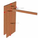
With all Locks off, should we change an Inset, Inset 1 for example, to 5 inches, when we press Enter the stretcher will move up until it is 5 inches from the top edge as shown. Notice in this case that Inset 2 has also changed. With Locks off, changing any inset moves the stretcher and also changes the opposite Inset.
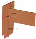
Now let’s go back to our original position (Inset 1 at 16.25” and Lock Inset 2 by placing a check in the checkbox. Then change Inset 1 to 5 inches and press Enter. Now, the only way to make Inset 2- 16.25” and Inset 1 - 5” is for the width of the stretcher to grow so that is what it did.
This demonstrates a key point in defining stretchers. The system will maintain the width of a stretcher unless the only way to satisfy Insets is to change the width of the stretcher, in which case it will change that width.
Locked Insets also help define what happens to the position of a stretcher as the cabinet size changes. Let’s say we have a nailer ( stretcher) at the very top of the back (Inset 1 = 0”). If we want that nailer to remain at the top even if the height of the cabinet changes, we should Lock Inset 1. If we then leave Inset 2 unlocked, the width of the stretcher will stay the same and it will always be located at the very top of the cabinet back.
In this case we would also want to lock Inset 4 to keep the nailer properly positioned against the back even with changes in cabinet depth.
This same idea works for the length of the stretcher. Inset 5 and inset 6 are both zero which means the stretcher just touches to cabinet ends. If we want the stretcher to remain exactly between the cabinet ends as the cabinet width changes we must Lock both Inset 5 and Inset 6.
This does not, however, work with the thickness of the stretcher. The system assumes that the stretcher is made from a specific material which has a fixed thickness. In this case, if we were to Lock Inset 3, Inset 4 is grayed out and cannot be changed.
The stretcher can also be rotated using the slide bar or designating the angle in the box. Remember, as soon as the stretcher is rotated, joinery between non perpendicular parts is lost. Also, once the stretcher is rotated, the image of the stretcher itself disappears and is replaced by the image of the bounding box. The bounding box is the smallest horizontal/vertical box that completely contains the rotated stretcher. Insets are measured from this bounding box for a rotated stretcher.
Press Done when complete, then return to the Main page by clicking the Main icon.
At this point, you can change construction (joinery) for the stretcher by right clicking on the stretcher and selecting Construction, then selecting the side you want to change and the joint you want.