 When you place a cabinet over
these, the pipe sticks through the back of the cabinet. If you hide the doors,
you can see the pipes inside the cabinet.
When you place a cabinet over
these, the pipe sticks through the back of the cabinet. If you hide the doors,
you can see the pipes inside the cabinet.
Adding cabinets to a room can be a bit confusing unless you know and understand how to use the available tools.
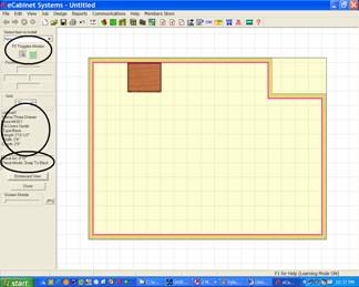
Items are placed in the layout in the Detail Room area reached by pressing the Detail Room button. In this area there are two “views”, an Overhead View and an Elevation View of a single wall. One of the things that can make this confusing is that certain items can be placed in the room from either the Overhead or Elevation view and others can only be placed from the Elevation View.
If you look to the upper left of the display in the Detail Room area you will see an area titled Items to Install. It contains a list of everything you can install in the room.
The first entry on this list is Item. If you select this you will see another list of various items starting with Cabinets. This entire list of items can be installed from either the overhead or the elevation view.
Under Items to Install, everything except the first selection (Item) can only be installed from the elevation view.
Let’s skip over Item and look at the remainder of the list then we will return and look at the various items that can be installed.
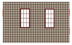
We discuss the Door and Window selections in the section titled “Placing Door and Window Images on a Wall”.
The next two, Water Pipe and Water Drain plus Cut Out and Vent are all utilities that are placed on a wall.
Early versions of the software envisioned these as utilities that the user could accurately place on walls, and then when the cabinets were placed in the room, the system could automatically add holes to the back of cabinets, or, shift the back of the cabinet forward to provide clearance for these utilities.
The ability to add the utilities to the wall remains, but the ability to automatically add clearance holes has not yet been developed.
Although the full functionality of these items is not complete, they are still a useful tool when laying out a room.
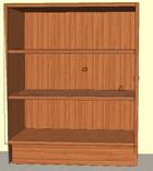
The pipes and drains display as copper colored pipes that stick straight out from the wall.
When you place a cabinet over
these, the pipe sticks through the back of the cabinet. If you hide the doors,
you can see the pipes inside the cabinet.
This can be quite useful when placing cabinets.
In the example shown, one pipe protrudes through the right side of the cabinet and another interferes with a shelf.
If you know about these problems before your layout is complete you may be able to shift the cabinet and/or move the shelf to avoid these kinds of problems during actual installation.
Of course, for this to be a truly useful tool, the walls and pipe locations must be accurately developed using precise measurements.
Available utilities include a Generic Cutout which is rectangular, a Vent, Water Pipe and Water Drain, which are all circular.
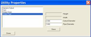 The size of each of these is
established by right clicking and selecting Sizable
Utility Properties.
The size of each of these is
established by right clicking and selecting Sizable
Utility Properties.
From the dialog you can select the item you wish to size.
Note that there are two dimensions for Vent, Water Pipe and Water Drain, Cutout Diameter and Pipe Diameter.
This goes back to the original purpose of these tools which was to actually place holes in the cabinet parts to provide utility clearance.
The Pipe Diameter is the size of the actual pipe or vent.
The Cutout Diameter is the size of the hole you want to clear the pipe or vent.
The pipe is the only part that extends away from the wall. If you do not place a cabinet over it, the actual Cutout Diameter can also be seen drawn on the wall around the pipe.
This is one of those areas open for future enhancement should eCabinet Systems Members indicate that it is something they are interested in.
The Light Switch and Electrical Outlet are both for display purposes, although the Light Switch does have one function that can be used, sometimes to great amusement, during presentations. Later in the Items area we will talk about placing lights in the room. If lights are placed in the room, they can be turned on and off and one way of turning the lights on and off is by clicking on a light switch.
The final selection for placement on the elevation view of a wall is called Snap Marker.
This is also a carryover from earlier versions but can prove useful in some circumstances.
The Snap Marker is simply a marker, somewhat like a pencil mark on a wall used to locate cabinets during placement. For example, if you want a cabinet in a specific location, you can place a snap marker in that location and then use it to accurately locate the cabinet. It is called a Snap Marker because the cabinet (provided you are in one of the snap modes) will snap to the marker for placement. Once you snap a cabinet onto a Snap Marker and place the cabinet, the Snap Marker disappears.
When working with Snap Markers it appears that the marker has thickness, in its actual use it is a two dimensional plane with zero thickness.
If you set a Snap Marker at two feet and butt the edge of a cabinet against it, the edge of the cabinet will be located precisely at two feet.
Now, we will move to installing cabinets, appliances and other items. As we said, these can be installed from either the Overhead or the Elevation View. We will start with the Overhead View.
Loading the cabinet is easy, however, it is initially a wireframe image that moves around with the mouse. This wireframe is moved into position and when you click the cabinet is placed. There are several modes used to place the cabinet in position.
Basically the mode tells the system how to align the cabinet with adjoining cabinets. You move the cabinet close to where you want it and it snaps into place. This also keeps you from installing one cabinet meshed with another. That is, except for the Freestyle Mode which does let you mesh cabinets together and yes, there are reasons you might want to do this.
When cabinets are placed in a room, they are positioned at a specific height above the floor and then can be moved around the room at this height. Base cabinets are installed on the floor, detached toe cabinets are installed at the height of the detached toe base and upper cabinets are installed at a specified height above the floor.
This default mounting height is on the floor for base cabinets, is set in Settings Preferences - Standard Dimensions for the upper cabinet and is set in the Cabinet/Assembly Editor - Construction Settings – Toe Kick for a detached toe cabinet.
If these aren’t acceptable, when you load a cabinet you can specify a mounting height by pressing the Change Size button. Once installed, mounting height can still be moved up or down should that be necessary.
Although we are working in the Overhead View, we can tilt the room front to back by using the PageUp and PageDn keys on the keyboard. This isn’t quite as flexible as the Main page where the room can be both tilted and rotated but you will find this to be a useful tool when trying to precisely fit things together in three dimensions.
Note that items still move parallel to the floor, even when the room is tilted.
You can return the tilted room to the Overhead View by pressing the Home key.
Now, let’s explore installing cabinets.
Select Item from the Select Items to Install list, check Cabinets and select a directory and cabinet to load. Note that you should click on the picture of the cabinet itself to select it and not the checkbox. The checkbox is used to identify cabinets that you want to delete. There is a Delete Checked Items button at the bottom of the dialog.
When you select a cabinet a blue bar appears and the size of the cabinet is displayed at the lower left.
This can be changed by clicking Change Size.
In addition to allowing us to change the size of the cabinet we can also change the height at which the cabinet is initially placed in the room.
If you have not developed your own library of cabinets yet, you can practice with the Framed cabinets in the Standard Cabinets directory. These are complete cabinets with slab doors.
Press OK and we have a wireframe of the cabinet.
As we move the mouse around, the wireframe follows. The way it acts in relation to other cabinets and the walls depends, however, on the Insert Item Method that is currently active.
Right click and select Insert Item Method.
The software supports four insert methods.
The first three Insert Item Methods all depict how a cabinet will react to other cabinets in the room.
- Align to Back aligns the new cabinet to the back of any existing cabinet it touches.
- Align to Front aligns the fronts.
- Align to Center aligns the centers.
These are all essentially the same if the cabinets are the same depth and only come into play if the two cabinets are different depth.
The fourth Insert Item Method, Free Style means you can put the cabinet anyplace you like regardless of what else might be in the way. The cabinet can be placed halfway through the wall or meshed with another cabinet. You are free to place it anyplace you want, hence the name Free Style.
There are actually practical reasons why you might want to mesh a cabinet with a wall or another cabinet.
For example, some cabinetmakers add a scribe to the outside of cabinet face frames which they trim during installation to precisely fit. The mesh ability allows you to design the cabinet box with the scribe and then mesh the portion that will be trimmed away into the wall.
As you work in this area you will soon see that measurements and fits are quite accurate.
If you create the room accurately, and build your cabinets accurately, the cabinets can be fit to a tolerance impossible to measure with a ruler.
Let’s look at the behavior of the cabinet and the room when working in the Detail Room area.
 The cabinet symbol will be the size
of the actual cabinet as you move it around.
The cabinet symbol will be the size
of the actual cabinet as you move it around.
The background grid in this area works much like it does in other area we have covered.
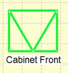
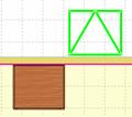
The cabinet symbol has a V in the center that points to the front of the cabinet as shown.
The basic orientation of the cabinet changes as the cabinet comes in contact with wall or other cabinets.
When it contacts a wall, it turns its back to the wall and aligns with the wall.
It does the same thing when it contacts another cabinet.
 If you are not in the Free Style mode, it snaps into alignment
with other cabinets when it touches them.
If you are not in the Free Style mode, it snaps into alignment
with other cabinets when it touches them.
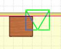
Here we are working in the Free Style mode. You see a cabinet meshed with another cabinet and a wall. It has turned so that its front points away from the wall but is meshed with the wall.
 If you continue to push it through
the wall, it will reverse orientation when it reaches the other side so that it
can be place on the other side.
If you continue to push it through
the wall, it will reverse orientation when it reaches the other side so that it
can be place on the other side.
Cabinets can be placed on both sides of a wall.
The red line you see on the wall indicates the position of the initial Wall Lines you developed in the Create Wall area. This is also defined as the front side of the wall.
If you are in the Free Style mode, the cabinet will move smoothly through the wall, changing orientation about halfway through.
If you are in any of the other modes, it will stop at the wall as you move and then snap to the other side of the wall if you keep moving the mouse.
There are two modes when working in Detail Room, Select/Move Mode and Insert Mode.
 Insert
Mode is used to initially load and position cabinets and assemblies. The Select/Move Mode is used to select
cabinets or items for any reason or to select and move these items after they
have been initially placed.
Insert
Mode is used to initially load and position cabinets and assemblies. The Select/Move Mode is used to select
cabinets or items for any reason or to select and move these items after they
have been initially placed.
The mode is selected using the icons at the upper left as shown.
They can also be selected by right clicking and selecting from the menu or they can be toggled using the F2 key.
The system automatically switches to the Insert mode when you select an item to install.
If you want to select an item after installation for any reason, you must switch to the Select/Move mode.
If you are in the Select/Move Mode and pause the cursor over an installed cabinet, information about that cabinet is shown in an area to the left of the display.
Under this display information is another display showing the current Move Increment, Pan Increment and the active Insert Item Method.
This might be a good time to talk about cabinet numbers.
Each cabinet is given a number when placed in a room.
Cabinet numbers become important as the layout grows and reports are generated.
Cabinets are numbered consecutively as they are placed in the layout. The first cabinet is number one, the second number two, etc.
When a cabinet is deleted from the layout, all other cabinets with higher numbers are renumbered so that there is a complete, unbroken list of cabinet numbers.
This can be important if you run interim reports such, as Cut Lists, that rely on cabinet numbers. It is possible to run and print a report and then delete a cabinet and change the cabinet number of many of the cabinets in the report, making the report inaccurate.
Also, cabinet can be entered into the job in the Batch Cabinets area. Cabinets entered in Batch Cabinets are not numbered in the same sequence as those entered in Custom Layout.
Now back to installing cabinets. As we have already said, the cabinet will rotate to match a wall or other cabinets when installing it.
There are times, however, when you might want a cabinet at a specific angle and not necessarily have it match the wall or other cabinet.
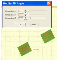
This is accomplished using the Modify Angle function.
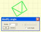 Right
click and select Modify Angle
to bring up the dialog shown.
Right
click and select Modify Angle
to bring up the dialog shown.
Use this to rotate the cabinet to any angle.
You can also Lock the angle.
If you do not Lock the angle, it will maintain the angle you selected until it touches something else at which time it will take on the angle of the item it touched.
These characteristics can make developing an angled island or peninsula relatively easy.
Specify and lock an angle for one cabinet and install it.
Then, as other cabinets touch it, they automatically take on the correct angle.
Once placed in the room, other functions allow you to further adjust the angle.
Switch to the Select/Move mode and highlight a cabinet.
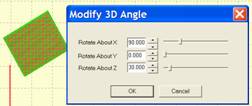
Right click and select Edit Object and then Rotate Object.
The dialog shown will appear.
Until now we have been rotating the cabinet around the Z Axis, as you might rotate it on the floor.
 This dialog also allows you to also
rotate the cabinet around the X and Y Axes. The cabinet could be laid on its
side or back or turned upside down and hung from the ceiling.
This dialog also allows you to also
rotate the cabinet around the X and Y Axes. The cabinet could be laid on its
side or back or turned upside down and hung from the ceiling.
This can actually be quite useful and becomes mandatory as the software begins to be used for designing items beyond cabinets.
rotate more than one item at a time.
You can highlight two or more cabinets, all the cabinets in an island for example, and then rotate them about their combined center.
When more than one cabinet is highlighted, rotation is again restricted to rotation about the Z Axis.
This function is automatically used when you select Modify Angle from the Right Click Menu and more than one cabinet is highlighted.
If a single cabinet is highlighted full 3D rotation is available.
The final point we want to make about installing cabinets is the mounting height of cabinets.
When a cabinet is designated as Upper, it is automatically installed a fixed distance above the floor.
This distance is specified in the Standard Dimensions area of Setting/Preferences.
This area also specifies other parameters about how cabinets are placed with respect to walls, appliances or other cabinets.
You can get to Standard Dimensions by either going to Settings/Preferences and selecting the Standard Dimension button, or there is a direct link to Standard Dimensions from the Right Click Menu.
You might want to go through the various settings to become familiar with the areas that are controlled from here.
Regardless of the upper cabinet mounting height set in Standard Dimensions you can change this using the Define Size dialog when you are installing a cabinet.
You can also adjust the height after the cabinet has been placed.
Cabinets can also be installed from the Elevation View. The Elevation View is essentially a face on view of a single wall.
To work in the Elevation View, you must understand the concept of Associations. In essence, each wall has certain items that are “Associated” with it. When you look at an Elevation View of a wall, the wall and all items that are associated with it are shown, regardless of their location in the room. Anything not associated with the wall is not shown.
So how are things “Associated” to a wall?
Anything placed from an Elevation View of a wall is automatically associated to that wall. Also, cabinets placed in the Overhead View that are located against a wall are generally associated to that wall.
We say “generally” because sometimes if the cabinet is not exactly against the wall the system may not associate it. Corner cabinets, placed tightly in a corner are associated with both walls it touches.
The final way to associate or disassociate items to a wall is by highlighting the item, then right clicking on the wall and selecting Associate to Wall or Disassociate From Wall from the menu selections.
You might also note that items can be associated with either one or two different walls.
Some functions available from the overhead view are not available in the elevation view. Duplicate Left, Duplicate Right and Auto Fill will not work in the elevation view because they must detect adjacent walls which are not present in the elevation view.
To get an elevation view of a wall, from Detail Room place the cursor on the wall and press the right mouse button. From the menu select Show Wall Elevation.
From Select Items to Install select Item, then select a directory and a base cabinet. Click OK.
From the Elevation View, cabinets are automatically placed against the wall. You will note that they can be moved left to right, in fact, they can be moved right off the wall.
In the Elevation View, there is nothing to stop the cabinets at either end of the wall. In the Overhead View, we have the adjoining walls for location. These are not available in the Elevation View of a single wall.
In this case, you have three choices.
You can simply eyeball the placement getting it as close as possible visually.
If you need precise location, you can use Snap Markers.
From the Select Items to Install select Snap Marker.
Install a snap marker on the left end by roughly positioning it and clicking
Make sure you set the height of the marker above the floor so that the cabinet will contact it. Unless a cabinet actually touches a Snap Marker it cannot be used to locate it.
Don’t worry about getting the position exactly perfect right now, just place it close to the left end of the wall.
Now, switch to the Select/Move Mode.
Highlight the Snap Marker by double clicking on it.
Now set the distance in the left dimension box to zero and press Enter.
You have now positioned the Snap Marker precisely at the edge of the wall. Press Esc to remove the highlight.
Here is what the wall now looks like (there are a couple of snap markers on the right side also).
Although the Snap Marker seems to have a width when we view it, in actual use it has a zero width. If we set it at zero, the edge of a cabinet touching it will be precisely at zero.
Now, switch back to the Place Item Mode and again select our cabinet. You will notice that when you move it over, the Snap Marker positions the cabinet correctly.
Note that when you install a cabinet against a Snap Marker, the Snap Markerdisappears, its job being complete.
Another way of locating cabinets at the ends of the walls is to simply place them on the wall but away from the end. Then, switch to the Select Move Mode, highlight the cabinet, set the distance on that side to zero and press Enter. The cabinet will move to the end.
Note that the functions that automatically resize the cabinet for a smaller opening or the Expand to Fill command works from the Elevation View.
The height of a cabinet can be adjusted from the Elevation View by highlighting the cabinet. Then you can either type the new height above the floor in the position box to the left or you can move it up or down using the up and down arrow keys. Each time the key is pressed, the cabinet moves the distance specified in the Move Increment.
Once items have been placed they can be further adjusted in several ways. We cover these adjustments in the section “Adjusting Installed Cabinets in Custom Layout”.